Eureka AIR delivers breakthrough ideas for toughest innovation challenges, trusted by R&D personnel around the world.

Microwave absorber composite material capable of achieving full frequency band absorption within range of 2-8 GHz

A technology of composite materials and microwave absorbing materials, which is applied in the field of absorber composite materials, can solve problems such as poor low-frequency absorption effect, difficulty in full-band absorption, narrow stealth frequency band, etc., and achieve the effect of widening the absorption bandwidth

Active Publication Date: 2016-07-27
HUNAN UNIV
View PDF6 Cites 3 Cited by
  • Summary
  • Abstract
  • Description
  • Claims
  • Application Information

AI Technical Summary

Problems solved by technology

However, whether it is ferrite, metal micropowder, polycrystalline iron fiber that has been widely used, or new microwave absorbers such as nanomaterials, two-dimensional materials, and frequency selective surfaces developed in recent years, there are still narrow frequency bands for stealth and poor low-frequency absorption effects. And other issues
At present, it is still difficult to achieve full-band absorption in the 2-8GHz frequency range

Method used


Image

  • Microwave absorber composite material capable of achieving full frequency band absorption within range of 2-8 GHz
  • Microwave absorber composite material capable of achieving full frequency band absorption within range of 2-8 GHz
  • Microwave absorber composite material capable of achieving full frequency band absorption within range of 2-8 GHz

Examples


Embodiment 1

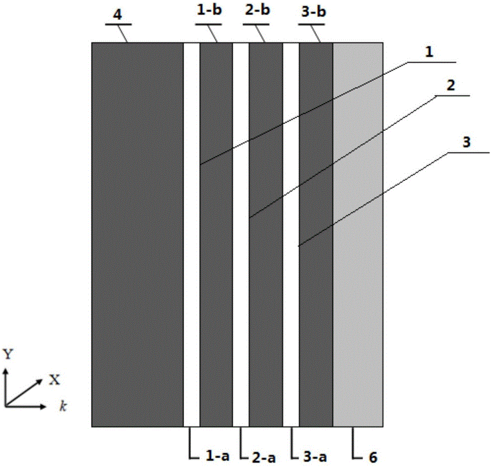
[0016] An absorber composite material that can achieve full-band absorption from 2 to 8GHz, such as figure 1 As shown, the k direction in the figure is the incident direction of electromagnetic waves, X is the direction of the electric field, and Y is the direction of the magnetic field; the three base units 1, 2 and 3 are superimposed from top to bottom, and the structures of the three base units are basically the same. One side of the microstructure material 1-a is coated with a microwave absorbing material with a thickness of 0.5 mm to form a microwave absorbing coating 1-b to form the base unit 1, and one side of the rectangular microstructure material 2-a is coated with a microwave absorbing coating with a thickness of 0.5 mm. The microwave absorbing material forms the microwave absorbing coating 2-b to form the base unit 2, and the microwave absorbing coating 3-b formed by the microwave absorbing material is coated with a thickness of 0.5mm on one side of the rectangular ...

Embodiment 2

[0018] The absorber composite material of embodiment 1 is prepared by the following method:

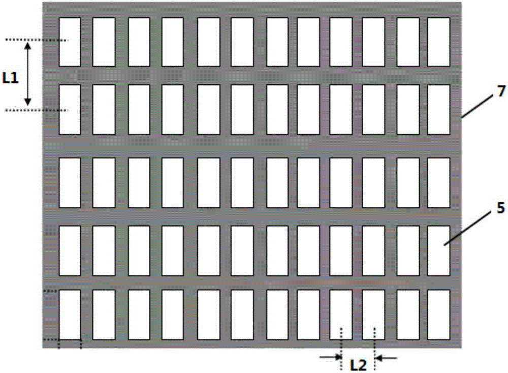
[0019] First, according to the design requirements that the distance between the upper and lower two adjacent metal copper sheets 5 is 10 mm, and the distance between the left and right two adjacent metal copper sheets 5 is 2.2 mm, the printing method in the prior art is applied on the glass fiber board. Cover its two sides with a rectangular metal copper sheet 5 with a thickness of 0.01mm to make three rectangular microstructure materials. The length of the rectangular metal copper sheet 5 of a rectangular microstructure material is 9.5mm and the width is 2.2mm. The length of the rectangular metal copper sheet 5 of the material is 6.8mm, and the width is 2.2mm, and the length of the rectangular metal copper sheet 5 of the third rectangular microstructure material is 5mm, and the width is 2.2mm; The powder and the binder epoxy resin are fully mixed in a mass ratio of 1:3 and then spra...

Embodiment 3

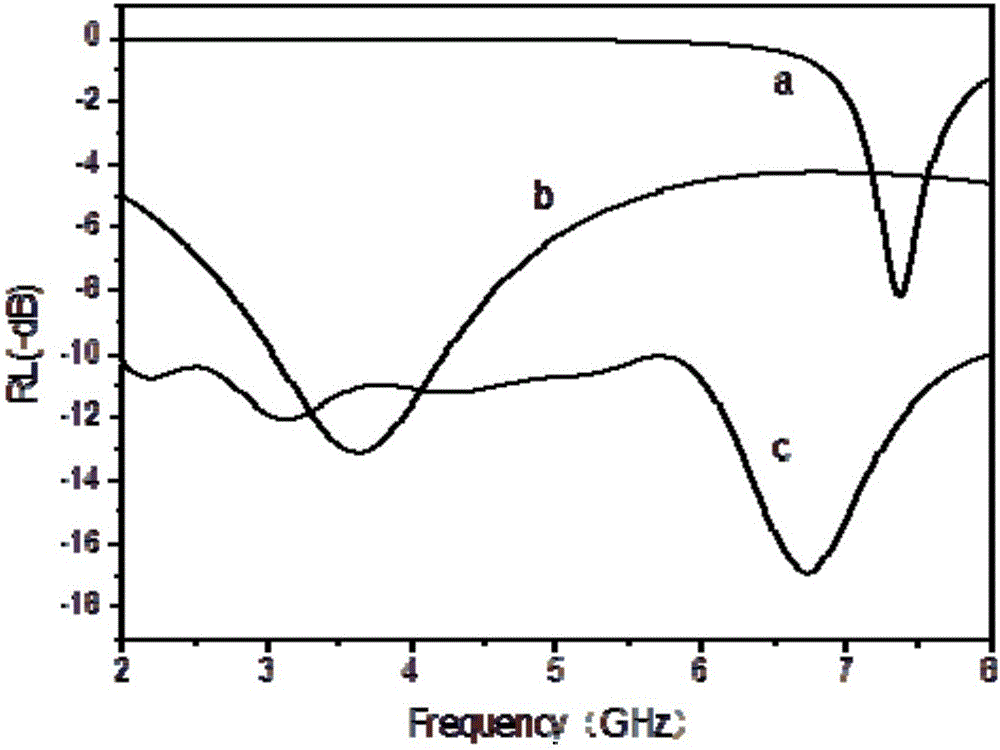
[0021] The frequency-reflection loss curves of the following three materials are measured respectively by the bow-shaped frame method, a single three-layer, single microwave-absorbing material carbonyl iron powder coating (thickness) composed of three rectangular microstructure materials as in Example 2 3.4mm) and the composite microwave absorbing material of embodiment 1, the results are shown in image 3 , in the figure a is the reflection loss curve of rectangular microstructure material with frequency, b is the reflection loss curve of traditional microwave absorbing material carbonyl iron powder coating with frequency, and c is the reflection loss curve of composite microwave absorbing material with frequency Curve. From image 3 It can be seen that the absorption peak of the rectangular microstructure material appears at 7.25GHz, and the reflection loss does not reach -10dB. The absorption frequency band is 3.4mm thick and the carbonyl iron powder microwave absorption ...


PUM

PropertyMeasurementUnit
Lengthaaaaaaaaaa
Widthaaaaaaaaaa
Lengthaaaaaaaaaa

Abstract

The invention provides a microwave absorber composite material capable of achieving full frequency band absorption within the range of 2-8 GHz.The microwave absorber composite material is formed by superimposing three base body units formed by covering rectangular micro-structure materials with microwave absorption materials, the rectangular micro-structure materials are formed in the mode that the two faces of inorganic non-metal plates are symmetrically covered with multiple rectangular metal sheets in sequence to form matrixes, the thicknesses of the rectangular metal sheets in the rectangular micro-structure materials in the base body units are the same, but the lengths or widths of the rectangular metal sheets are sequentially increased; a microwave absorption material coating is formed on the upper side face of the rectangular micro-structure material of the base body unit on the uppermost layer, wherein the thickness value of the microwave absorption material coating is larger than that of a microwave absorption material coating of the base body unit, and a supporting plate is coated with a microwave absorption material coating of the base body unit on the lowest layer.According to the material, under the condition that overall thickness is slightly increased, the microwave absorption frequency band is moved in the low frequency direction by controlling the sizes of the three rectangular micro-structure materials, absorption bandwidth is greatly increased, reflection losses within the frequency range of 2-8 GHz are lower than -10 dB, and full frequency band absorption is truly achieved.

Description

technical field [0001] The invention relates to a wave-absorbing body composite material, in particular to a wave-absorbing body composite material capable of realizing full frequency band absorption. Background technique [0002] Microwave absorbing materials are the key to the development of stealth technology, and countries all over the world are making every effort to develop various new microwave absorbing materials. However, whether it is ferrite, metal micropowder, polycrystalline iron fiber that has been widely used, or new microwave absorbers such as nanomaterials, two-dimensional materials, and frequency selective surfaces developed in recent years, there are still narrow frequency bands for stealth and poor low-frequency absorption effects. And other issues. At present, it is still difficult to achieve full-band absorption in the 2-8GHz frequency range. Contents of the invention [0003] The invention aims to provide a wave-absorbing composite material capable...

Claims


Application Information

Patent Timeline
IPC IPC(8): B32B17/02B32B17/06B32B15/085B32B15/20B32B27/32B32B3/08B32B33/00B32B37/02C03C17/00C08J7/04C09D163/00C09D5/32
CPCB32B3/085B32B5/02B32B15/085B32B15/14B32B15/20B32B17/061B32B27/08B32B27/322B32B33/00B32B37/02B32B2255/02B32B2255/06B32B2255/10B32B2255/26B32B2262/101C03C17/009C03C2217/475C03C2217/70C08J7/0427C08J2327/18C08J2463/00C09D5/32C09D163/00
Inventor 邹艳红张子龙杨丽陈喜桥刘洪波
Owner HUNAN UNIV
Why Eureka
Eureka Blog
Learn More