Pyrolysis device and method

A technology of pyrolysis and pyrolysis products, which is applied in the heating of coke ovens, special forms of dry distillation, and the petroleum industry. It can solve the problems of collection and separation difficulties, pyrolysis products that cannot be directly sold as products, and are difficult to use. Good pyrolysis effect

Active Publication Date: 2016-07-27
SHENWU TECH GRP CO LTD
View PDF3 Cites 2 Cited by
  • Summary
  • Abstract
  • Description
  • Claims
  • Application Information

AI Technical Summary

Problems solved by technology

[0003] Pyrolysis and gasification processes mostly use different furnace types (such as fixed bed pyrolysis process, moving bed pyrolysis process, fluidized bed pyrolysis process, and rotary kiln pyrolysis process, etc.) to obtain different products. In the pyrolysis process, the operation and control of the pyrolysis equipment is simple, and the adaptability is strong, but the material in the furnace is heated unevenly, and there is a phenomenon of melting and coking, so it cannot run continuously; in the moving bed pyrolysis process, although the material has relative movement in the furnace, However, the relative movement between the particles is small, the heating is still uneven, and the pyrolysis efficiency is low; in the fluidized bed pyrolysis process, although the pyrolysis equipment can operate continuously, using inert gas or particles as the heat carrier to heat the material, the heat transfer performance is good , it is easy to achieve temperature control, and there is less melting and coking, but the use of fluidizing gas reduces the calorific value of pyrolysis gas, and the equipment is complicated and difficult to operate; Simple, wide adaptability, good heat transfer effect, but the rotary kiln is bulky, difficult to seal equipment connections, and the inherent problem of coking and ringing cannot be effectively solved
[0004] In addition, the reasons why the above-mentioned devices cannot fully realize continuous operation include the following points: (1) The produced product pyrolysis oil has high viscosity, complex composition, and low calorific value, making it difficult to further utilize it. The oil will also block the pipeline, corrode the equipment, affect the normal operation of production, and make it difficult to collect and separate; (2) The overall system is relatively complicated, requiring multiple separation and purification processes, and the energy utilization efficiency is low; (3) The pyrolysis product cannot be used as a product Direct sale requires further processing and refining, which makes the process system actually an incomplete system and cannot truly realize industrial production

Method used


Image

  • Pyrolysis device and method
  • Pyrolysis device and method

Examples


Embodiment 1

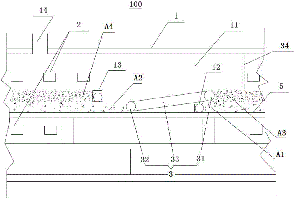
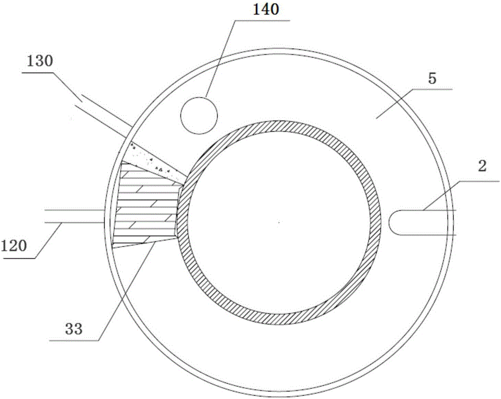
[0067] The pyrolysis device 100 of this embodiment is a radiation pyrolysis furnace, including: a furnace body 1, a feeding device 120, a discharging device 130, a gas collection pipeline 140, a material spreading plate 5, a heating device 2, and a material discharging device 3, etc.

[0068] Specifically, the furnace body 1 is generally formed as a cylinder with a circular cross-section, including: the peripheral wall of the furnace body, the peripheral wall of the furnace body, the top wall of the furnace body and the bottom wall of the furnace body, wherein the peripheral wall of the furnace body and the peripheral wall of the furnace body are formed It is cylindrical, and the peripheral wall of the furnace body is sleeved in the peripheral wall of the furnace body. The top wall of the furnace body and the bottom wall of the furnace body are both formed in a circular shape, and the top wall of the furnace body is fixedly connected to the top of the peripheral wall of the furn...

Embodiment 2

[0080] The structure of the pyrolysis device in the second embodiment is basically the same as that of the pyrolysis device 100 in the first embodiment, the difference is that the feeding device 120 in the pyrolysis device in the second embodiment is not a screw feeder but a bar feeder. Squeeze feeder.

[0081] Hereinafter, the method for pyrolyzing municipal sludge raw materials using the pyrolysis device of the second embodiment will be briefly introduced.

[0082] Specifically, this method is basically the same as the above-mentioned method of pyrolyzing straw raw materials using the pyrolysis device 100 of Embodiment 1, the difference is that: in the process of obtaining pyrolysis raw materials, municipal sludge is dried and pretreated, A pyrolysis raw material with a water content of 30% is obtained; the thickness of the pyrolysis raw material input to the laying board 5 is 50 mm; the time for the laying board 5 to rotate once is 1 hour.


PUM


Abstract

The invention discloses a pyrolysis device and method. The pyrolysis device comprises a furnace, a heating device and a transfer device. The furnace comprises a hollow annular cavity, an annular laying plate capable of horizontally rotating is arranged on the bottom face of the cavity, a feeding port and a discharging port are formed in the side wall of the cavity, and the arrangement height of the discharging port is larger than that of the feeding port. The heating device is used for providing a heat source for pyrolysis. The transfer device is arranged in the cavity and comprises a first roller, a second roller and a lifting belt. In the operating direction of the laying plate, the first roller is arranged on the downstream side of the feeding port, and the second roller is arranged on the downstream side of the discharging port. In the vertical direction, the first roller is located above the feeding port and is adjacent to the feeding port, the second roller is located below the discharging port and is adjacent to the discharging port, and the lifting belt is arranged on the first roller and the second roller in a sleeving mode to cyclically roll. According to the pyrolysis device, the pyrolysis effect is good.

Description

technical field [0001] The invention relates to the field of resource utilization of organic solid waste, in particular to a pyrolysis device and a pyrolysis method. Background technique [0002] The pyrolysis products of solid waste are as follows: combustible gas, including some low-molecular hydrocarbons such as hydrogen, methane, carbon monoxide, etc., which can be used as low calorific value fuel gas; pyrolysis oil, theoretically part of the pyrolysis oil is refined It can be used as fuel oil; pyrolytic carbon, mostly in the form of carbon black, can be further processed for energy applications. This mixture includes pure carbon, glass, earth sand, metal, etc. [0003] Pyrolysis and gasification processes mostly use different furnace types (such as fixed bed pyrolysis process, moving bed pyrolysis process, fluidized bed pyrolysis process, and rotary kiln pyrolysis process, etc.) to obtain different products. In the pyrolysis process, the operation and control of the py...

Claims


Application Information

Patent Timeline
Patent Type & Authority Applications(China)
IPC IPC(8): C10B53/00C10B23/00
CPCC10B23/00C10B53/00
Inventor 贾懿曼肖磊巴玉鑫张安强吴道洪
Owner SHENWU TECH GRP CO LTD
Why Eureka
Try Eureka