Under-pressure well repairing working device and method of oil-gas field

A kind of operating device and oil and gas field technology, which is applied in the direction of wellbore/well valve device, earthwork drilling and production, wellbore/well components, etc., which can solve the problems of lowering the pressure level, having to shut down the well for maintenance, and low safety factor, so as to reduce the Pressure level, reducing workover energy consumption, and improving service life

Active Publication Date: 2016-07-27
崔斌
View PDF10 Cites 8 Cited by
  • Summary
  • Abstract
  • Description
  • Claims
  • Application Information

AI Technical Summary

Problems solved by technology

[0010] In order to solve many problems in the traditional workover operation method, such as polluted formation, low safety factor, long time, high energy consumption, well shut-in and maintenance, etc., the present invention provides a pressurized workover operation device and method for oil and gas fields. The well pressure is controlled below the production pressure of the station to realize maintenance without shutting down the wel

Method used


Image

  • Under-pressure well repairing working device and method of oil-gas field
  • Under-pressure well repairing working device and method of oil-gas field

Examples


Embodiment 1

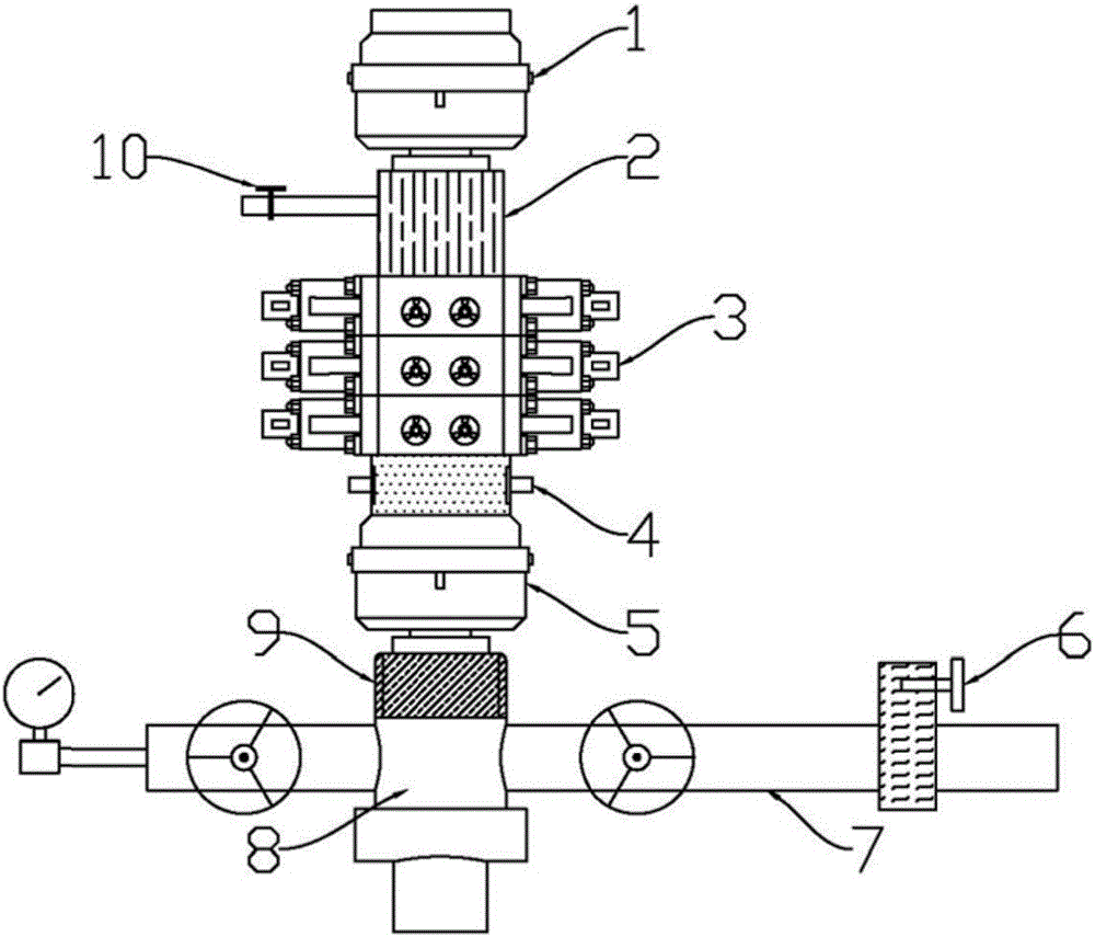
[0049] like figure 1 As shown, the present invention discloses a pressurized workover operation device for oil and gas fields, including a constant pressure valve 6 installed on the original production pipeline 7 of the station, and the pressure setting value of the constant pressure valve 6 is within the original production pipeline 7 of the station. pressure. During the workover process, when the pressure in the well is higher than this pressure, the oil, gas and water will be sent into the production pipeline 7 by the automatic pressure relief of the constant pressure valve 6 . The upper part of the four-way 8 is sequentially installed with a coupling detector 9, a lower annular blowout preventer 5, a built-in hydraulic elevator 4, a three-ram blowout preventer 3, a casing nipple 2, and an upper annular blowout preventer 1. The upper annular blowout preventer 1 and the lower annular blowout preventer 5 all have a rubber inner core, and the upper annular blowout preventer 1...

Embodiment 2

[0080] This embodiment is a workover operation under pressure in the case of a gas lift production string. The method is similar to the method in Example 1. Install a constant pressure valve 6 on the pipeline entering the station or into the gathering and transportation system, and set the original entering station pressure as the working pressure of the constant pressure valve 6. When the wellbore pressure exceeds this pressure, the pressure will be automatically released into the gathering and transportation system.

[0081] S1, the steps of starting the tube:

[0082] S11, install the constant pressure valve 6 on the inbound pipeline, install the blowout prevention standpipe on the uppermost gate, open each gate in turn so that the tool can pass through the gate and the wellhead device and go down the oil pipe to the upper part of the first gas lift valve; wire work Plug the oil pipe plug under the equipment to the upper part of the first gas lift valve, and block the uppe...

Embodiment 3

[0094] This implementation is somewhat similar to the second embodiment, the difference is that in this embodiment, a gas lift string with a smaller diameter is lowered into the original production string.

[0095] S1, remove the devices above the main gate of the oil and gas production tree, and install the small cross, the lower annular BOP 5, the three-ram BOP 3, the casing nipple 2, and the upper annular BOP 1 above the main gate in sequence , Oil pipe injection head; connect the constant pressure valve to the incoming pipeline and set the original incoming pressure as the working pressure of the constant pressure valve;

[0096] S2. Use the injection head to lower the gas lift string with liner plug. When the weight of the tubing can overcome the upward force and sealing friction resistance generated by the pressure in the well on the sealing part of the tubing, use the workover rig to lower the tubing and tools. A special check valve is arranged on the upper part of each...


PUM


Abstract

The invention discloses an under-pressure well repairing working device and method of an oil-gas field. The device comprises a fixed-pressure valve mounted on a getting-in production pipeline; the upper part of a four-way joint is provided with a coupling detector, a lower annular anti-spraying device, a built-in hydraulic lift sub, a three-flashboard anti-spraying device, a sleeve short section and an upper annular anti-spraying device in sequence; the device further comprises a hydraulic control cabinet; the hydraulic control cabinet is connected with the built-in hydraulic lift sub, the three-flashboard anti-spraying device, the upper annular anti-spraying device and the lower annular anti-spraying device respectively; the method comprises the following steps: S1, a sucker rod works; S2, an oil pumping rod, a pump and other tools work. The well repairing working device and method, disclosed by the invention, completely break through a bottleneck of traditional well repairing work; well repairing pressure can be controlled to be lower than getting-in production pressure so that a pressure grade of needed equipment is reduced, the machining and manufacturing cost of the equipment is greatly reduced and the operation cost of an oil-gas well is reduced; furthermore, the difficulty that the well can be repaired only if the well is closed is innovatively overcome.

Description

technical field [0001] The invention relates to the technical field of oil and gas field exploitation, and more specifically relates to a pressure workover operation device and method for an oil and gas field. Background technique [0002] In the process of developing oil and gas fields, such as formation pressure changes, downhole accidents, changes in production methods, process technology, adjustment of production formations, etc., it is often necessary to carry out workover operations. The workover operation mainly includes the following steps: 1. The workover equipment pulls out the pipe string in the original well; 2. Runs in the new pipe string, tools and equipment. [0003] For workover operations, traditional workover methods can be classified into two types: [0004] 1. Use kill fluid: drive the kill fluid into the well with a high-pressure pump, wash and kill the well in a circular manner, press the well with the pressure generated by the liquid column to avoid b...

Claims


Application Information

Patent Timeline
IPC IPC(8): E21B33/00E21B34/00E21B33/06
CPCE21B33/00E21B33/06E21B34/00
Inventor 崔斌于雷
Owner 崔斌
Why Eureka
Try Eureka