Normal temperature and pressure micro-order heat stability test system and method

A thermal stability and test system technology, applied in the thermal development of materials, measuring devices, instruments, etc., can solve problems such as high cost, numerous influencing links, complex system design, etc., to eliminate the influence of test noise, ensure test accuracy, and system Create convenient effects

Active Publication Date: 2016-08-03
BEIJING INST OF SPACECRAFT SYST ENG
View PDF8 Cites 7 Cited by
  • Summary
  • Abstract
  • Description
  • Claims
  • Application Information

AI Technical Summary

Problems solved by technology

Due to the high requirements for test accuracy and test environment, the test of the thermal expansion coefficient at the specimen level is gradually becoming mature, but there is no mature test method for the thermal deformation test of the component level and large-scale structures.
According to ESA design standards, foreign language model reports and other documents and information research results, the thermal deformation tests carried out by foreign research institutions are mainly carried out in vacuum tanks and environmental simulation boxes, with corresponding complex test equipment and corresponding auxiliary devices, etc. , there are many influencing links, the system design is relatively complicated, and the cost is high. It cannot be implemented in domestic applications in the short term and still has the above problems
The existing domestic thermal deformation measurement equipment is mainly concentrated in the field of machinery manufacturing, such as precision forging die thermal deformation detection system and its detection method (CN102890097A), three-dimensional high-precision multifunctional thermal deformation experimental device (CN2700874Y), temperature and thermal Deformation comprehensive monitoring system and monitoring method (CN102166722A), its purpose is to monitor the thermal deformation perform

Method used


Image

  • Normal temperature and pressure micro-order heat stability test system and method
  • Normal temperature and pressure micro-order heat stability test system and method

Examples


Embodiment Construction

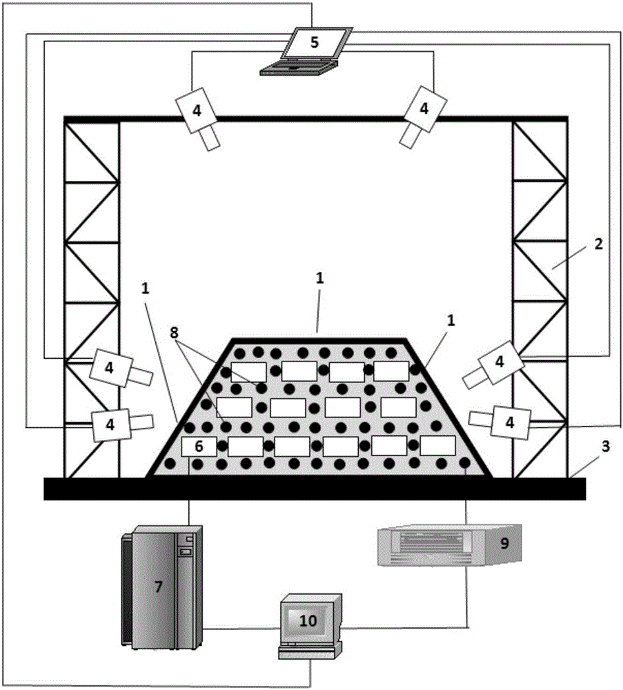
[0027] Such as figure 1 As shown, the normal temperature and pressure micron thermal stability test system includes a support frame 2, a support platform 3, a CCD camera 4, an image processing computer 5, a thermal control heater 6, a thermal control program control power supply 7, a temperature measuring element 8, a thermal control A temperature measurement acquisition card 9, a thermal control computer 10; the measured object is a measurement structure 1.

[0028] Both the measurement structure 1 and the support frame 2 are fixed on the support platform 3; the CCD camera 4 is installed on the support frame 2, and the installation position is such that the CCD camera 4 monitors the installation surface of the measurement structure 1 and the outer surface of the main support structure; the image processing computer 5 It is connected with the CCD camera 4; the thermal control heater 6 and the temperature measuring element 8 are arranged on the surface of the measurement struct...


PUM


Abstract

The invention provides a normal temperature and pressure micro-order heat stability test system and method. The test system comprises a supporting frame, a supporting platform, a CCD camera, an image processing computer, a thermal control heater, a thermal control and program control power source, a temperature measuring element, a thermal control temperature measuring collecting card and a thermal control computer. A tested object is a measuring structure. The measuring structure and the supporting frame are fixed to the supporting platform. The CCD camera is installed on the supporting frame, wherein the installation position meets the condition that the CCD camera can monitor the installation face of the measuring structure and the outer surface of a main supporting structure. The image processing computer is connected with the CCD camera. The thermal control heater and the temperature measuring element are arranged on the surface of the measuring structure, and the thermal control and program control power source is connected with the thermal control heater. The thermal control temperature measuring collecting card is connected with the temperature measuring element, and the thermal control computer is connected with the thermal control and program control power source and the thermal control temperature measuring collecting card. By means of the test system and method, the influence of test noise can be effectively eliminated, and the test precision under the normal temperature and pressure can be ensured.

Description

technical field [0001] The invention belongs to the technical field of spacecraft thermal stability testing, and in particular relates to a micron-level thermal stability testing system and testing method at normal temperature and pressure. Background technique [0002] High precision, high stability, and high agility have become typical features of a new generation of high-performance spacecraft. As one of the key elements, the on-orbit dimensional stability of the mechanical support system directly affects key imaging components such as cameras, antennas, star sensors, and gyroscopes, as well as data reception. The geometric relationship with the transmission components and attitude control components and between them is one of the important factors that determine the image positioning accuracy, camera imaging quality, and data transmission quality. At present, internationally renowned aerospace research institutions represented by NASA and ESA have carried out long-term r...

Claims


Application Information

Patent Timeline
IPC IPC(8): G01N25/20G01B11/16
CPCG01B11/16G01N25/20
Inventor 刘国青罗文波阮剑华白刚蔡铮孙腾飞童叶龙王杰利杨文涛张国斌杨国巍戴超曾福明杨巧龙史文华高峰钱志英
Owner BEIJING INST OF SPACECRAFT SYST ENG
Why Eureka
Try Eureka