Plasma cladding direct manufacturing rapid prototyping apparatus and method

A technology of plasma cladding and forming equipment, applied in the field of ion cladding direct manufacturing rapid prototyping equipment, can solve the problems of large wire diameter, difficulty in realizing rapid prototyping of ceramic and composite material parts, and uneven surface of parts, etc.

Inactive Publication Date: 2016-09-07
SINOADDITIVE MFG EQUIP CO LTD
View PDF10 Cites 8 Cited by
  • Summary
  • Abstract
  • Description
  • Claims
  • Application Information

AI Technical Summary

Problems solved by technology

This makes SLM rapid prototyping equipment expensive to run
[0009] Third, the laser is the core component of the selective laser rapid prototyping equipment, but the price of the laser is high and the maintenance cost is high
This makes the equipment cost of laser rapid prototyping technology very high
[0010] Fourth, the laser power is low, and the forming efficiency of parts is low
However, the above-mentioned laser cladding molding equipment and method mainly have the following three problems: first,

Method used


Image

  • Plasma cladding direct manufacturing rapid prototyping apparatus and method
  • Plasma cladding direct manufacturing rapid prototyping apparatus and method
  • Plasma cladding direct manufacturing rapid prototyping apparatus and method

Examples


Embodiment 2

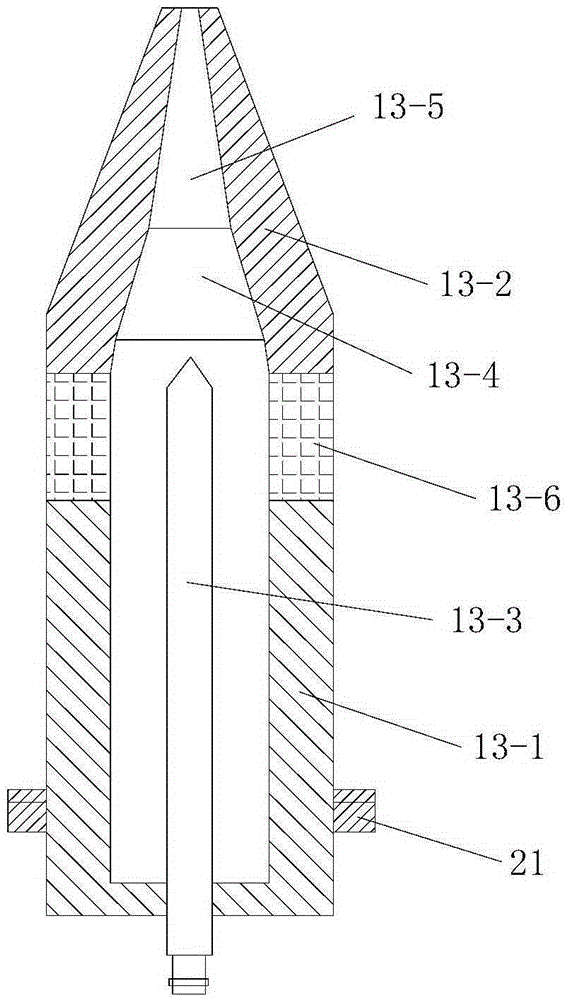
[0172] In this example, if Figure 7 As shown, the difference between the plasma cladding direct manufacturing rapid prototyping equipment used and the embodiment 1 is that the angle between the nozzle 13-5 and the central axis of the gun body 13-1 is 30°-45°.

[0173] In this way, after changing the direction of the plasma beam through the nozzle 13-5, the thermal load impact of the plasma jet on the anode nozzle 13-2 can be effectively reduced, and the anode ablation condition is improved.

[0174] In this embodiment, the structure, connection relationship and working principle of the rest of the rapid prototyping equipment directly manufactured by plasma cladding are the same as those in Embodiment 1.

[0175] In this embodiment, the plasma cladding direct manufacturing rapid prototyping method adopted is the same as that in Embodiment 1.


PUM

PropertyMeasurementUnit
Heightaaaaaaaaaa

Abstract

The invention discloses a plasma cladding direct manufacturing rapid prototyping apparatus and method. The device consists of a monitoring system, a plasma beam machining system and multiple print platforms. Each print platform includes a horizontal print station, a print station position adjusting device and an electric walk mechanism. The plasma beam machining system consists of a plasma generator, a print distance adjusting device, a gas supply device and a powder feeder. The monitoring system includes a walk controller, a plurality of walk position detecting units, a temperature detecting unit, a distance detecting unit and a print distance adjusting controller. The method comprises the steps of first, acquisition of a three-dimensional model of a workpiece to be prototyped and layered slicing processing; second, scan path filling; third, print path acquisition; and fourth, printing layer by layer from the bottom to the top. The invention is reasonable in design, simple to operate, high in prototyping efficiency and good in using effect, and requires neither a closed prototyping room nor a protective atmosphere or vacuum environment, with the workpiece prototyping process performed directly under atmospheric conditions.

Description

technical field [0001] The invention belongs to the technical field of rapid prototyping, and in particular relates to a rapid prototyping equipment and method directly produced by plasma cladding. Background technique [0002] 3D printing, known as Additive Manufacturing (AM) in academic circles, is a technology that uses computer design data to manufacture physical objects by layer-by-layer accumulation of materials. This technology started from the rapid prototyping technology in the 1980s and has three characteristics: one is a major leap in manufacturing technology. 3D printing is an emerging digital manufacturing technology that was born out of the integration of digital technology and manufacturing technology; the second is a profound change in the manufacturing process. 3D printing has changed the traditional cutting process mode, greatly reduced the processing steps, and can significantly shorten the development cost and cycle of new products; the third is an impor...

Claims


Application Information

Patent Timeline
IPC IPC(8): B22F3/105B33Y10/00B33Y30/00
CPCY02P10/25
Inventor 华云峰
Owner SINOADDITIVE MFG EQUIP CO LTD
Why Eureka
Try Eureka