Dynamic and static current-sharing and multi-chip paralleled power module

A power module and multi-chip technology, applied in semiconductor/solid-state device components, semiconductor devices, electrical components, etc., can solve the problems of increased switching loss, etc., achieve the effect of solving current sharing problems, improving utilization rate, and reducing side effects

Inactive Publication Date: 2016-09-07
CHONGQING UNIV
View PDF3 Cites 16 Cited by
  • Summary
  • Abstract
  • Description
  • Claims
  • Application Information

AI Technical Summary

Problems solved by technology

In order to solve this problem, some studies have used the method of source inductance compensation to reduce the inhomogeneity of parasitic parameters between different current branches and improve the current sharing effect of the module. However, this method also introduces additional parasitic inductance. may result in increased switching losses
In view of the shortcomings of existing layouts, some technologies have proposed some new DBC layout methods to reduce the imbalance between parasitic parameters, but these new layouts cannot guarantee that each branch is completely symmetrical, so It is still inevitable that there will be current sharing problems

Method used


Image

  • Dynamic and static current-sharing and multi-chip paralleled power module
  • Dynamic and static current-sharing and multi-chip paralleled power module
  • Dynamic and static current-sharing and multi-chip paralleled power module

Examples


Embodiment Construction

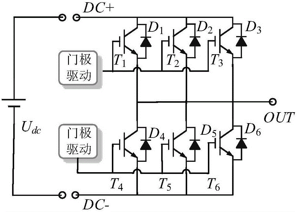
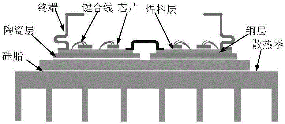
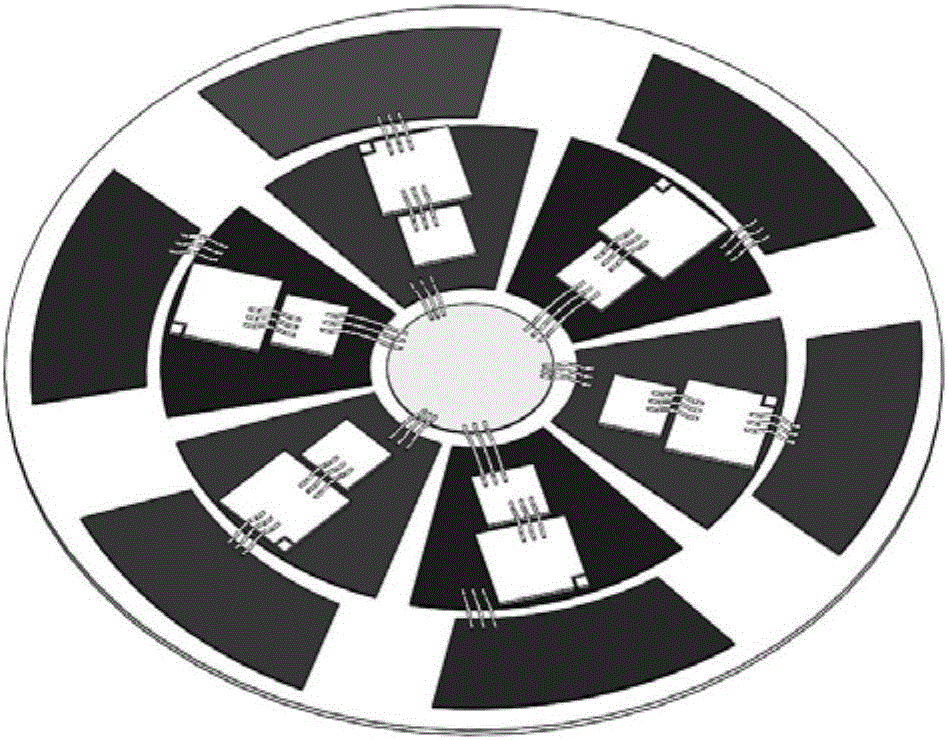
[0032] The present invention will be further described below in conjunction with accompanying drawing and embodiment: figure 1 It is the equivalent circuit diagram of the multi-chip parallel module of the present invention. figure 2 It is a cross-sectional schematic diagram of the multi-chip parallel module of the present invention. image 3 It is a schematic diagram of the symmetrical layout of the multi-chip parallel module DBC of the present invention. Figure 4 It is a structural schematic diagram of the drive and power terminals of the power module of the present invention. Figure 5 It is a schematic diagram of a calculation example for calculating parasitic inductance by the multi-chip parallel module analysis method of the present invention. Image 6 It is a schematic diagram of the dynamic characteristic test when three chips are connected in parallel in the present invention. Figure 7 It is a comparison diagram of the dynamic current sharing effect of the three-...


PUM


Abstract

The invention provides a dynamic and static current-sharing and multi-chip paralleled power module. The dynamic and static current-sharing and multi-chip paralleled power module comprises ceramic copper-clad plates and multiple power chips; various power chips are arranged on the ceramic copper-clad plates having the same structures in one-to-one correspondence; and the ceramic copper-clad plates are arranged in the circumferential direction in an axially symmetrical manner. According to the dynamic and static current-sharing and multi-chip paralleled power module disclosed by the invention, the symmetry of electrical parameters is realized through circular physical symmetrical structure; due to the optimized layout design, various branch parasitic parameters of the multi-chip paralleled power module are minimized; furthermore, distribution of various branch parasitic parameters is basically same; the non-uniform current distribution problem of the multi-chip paralleled module is solved easily; the multi-chip module design method disclosed by the invention can be used for realizing dynamic current-sharing and static current-sharing of the power module better; the capacity utilization rate of the power module is increased; and furthermore, the dynamic and static current-sharing and multi-chip paralleled power module is adaptive to a fast switching process and a high-frequency power electronic converter by reducing the side effects of a parasitic inductance.

Description

technical field [0001] The invention relates to the field of power electronics, in particular to a dynamic and static current sharing multi-chip parallel power module. Background technique [0002] In recent years, power electronic devices have been widely used in new energy power generation systems, motor drives and electric drives. As the industry puts forward higher and higher demands on power electronics, the switching frequency of power electronic devices is getting higher and higher to increase power density, but the switching speed of power modules based on Si (silicon) devices has basically reached the physical limit. Therefore, The industry has begun to turn its attention to wide bandgap devices such as SiC (silicon carbide) and GaN (gallium nitride). Compared with Si devices, the electrical and thermal characteristics of wide bandgap materials are more excellent. SiC MOSFET (metal oxide semiconductor field effect transistor) has higher thermal conductivity, blocki...

Claims


Application Information

Patent Timeline
Patent Type & Authority Applications(China)
IPC IPC(8): H01L25/04H01L25/07H01L23/528
CPCH01L23/528H01L25/04H01L25/072H01L2224/48091H01L2924/00014
Inventor 曾正邵伟华冉立胡博容
Owner CHONGQING UNIV
Why Eureka
Try Eureka