
Double-electron-beam double-grating based terahertz free electron laser source

A double electron injection and double grating technology, applied in the field of vacuum electronics, can solve the problem of low radiation power

Active Publication Date: 2016-09-14
UNIV OF SCI & TECH OF CHINA
View PDF3 Cites 13 Cited by
  • Summary
  • Abstract
  • Description
  • Claims
  • Application Information

AI Technical Summary

Problems solved by technology

[0005] The traditional Oro tube is based on the incoherent Smith-Purcell radiation of the electron beam. In order to excite and amplify the standing wave field in the open resonator, the electron beam needs to have a very high current density, the emission ability of the cathode and the bunching of the electron beam bring great challenges
At the same time, the radiation power of traditional Oro tubes in the terahertz frequency band (especially when the frequency is close to and exceeds 1THz) is extremely low, usually less than 1 milliwatt, which is far from meeting the needs of practical applications

Method used


Image

  • Double-electron-beam double-grating based terahertz free electron laser source
  • Double-electron-beam double-grating based terahertz free electron laser source
  • Double-electron-beam double-grating based terahertz free electron laser source

Examples


Embodiment 1

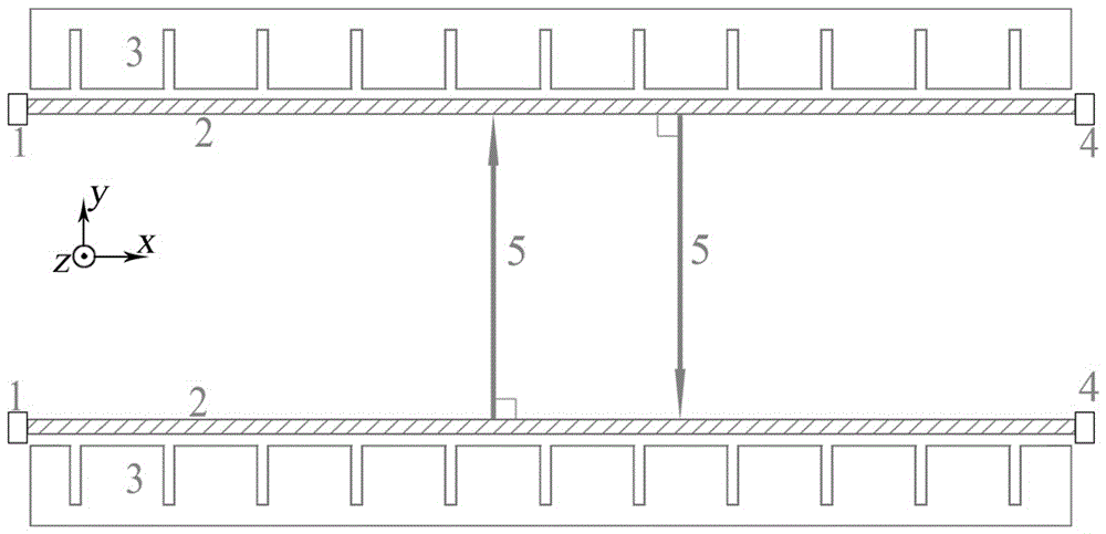
[0035] see figure 1 , a terahertz free electron laser source based on double electron injection and double gratings includes two sets of electron guns 1 with identical parameters, metal rectangular gratings 3 and collectors 4 . The two electron guns 1 correspond to the two collectors 4 respectively, a metal rectangular grating 3 is located between the electron gun 1 and the collector 4 on one side, and the other metal rectangular grating 3 is located between the electron gun 1 and the collector on the other side 4, two metal rectangular gratings 3 are symmetrical; the two metal rectangular gratings 3 form a variant open resonant cavity.

[0036] In this embodiment, the terahertz free electron laser source works in the fundamental mode, the radiation frequency is 0.32THz, and the radiation power is 10W.

[0037] The working parameters of the terahertz free electron laser source in this embodiment are as follows: the grating period is 0.13 mm, the gap width between the grating ...

Embodiment 2

[0041] The structure of the terahertz free-electron laser source based on double-electron injection and double-grating is the same as that in Embodiment 1.

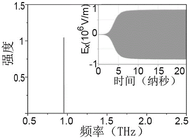
[0042] In this embodiment, the terahertz free electron laser source works in the secondary mode, and the radiation frequency is 0.96 THz.

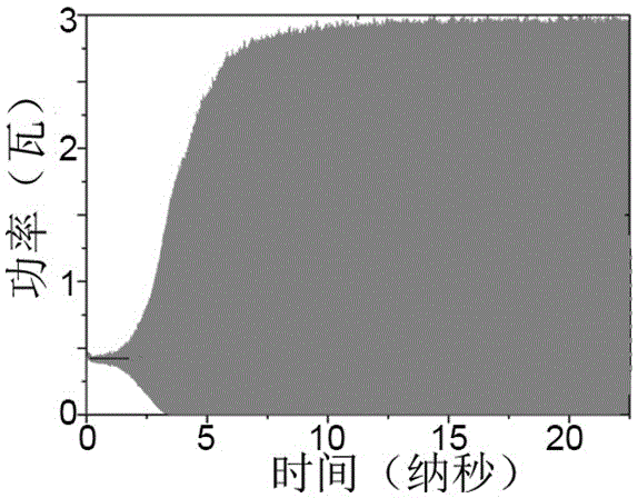
[0043] The specific implementation parameters and simulation results of this embodiment are as follows: the grating period is 0.13 mm, the gap width between the grating comb teeth is 0.013 mm, the grating comb tooth depth is 0.215 mm, and the distance between the two gratings is 2.2 mm; the cross-sectional size of the electron beam is 1mm*0.1mm, the electron beam acceleration voltage (i.e. working voltage) is 5 kV, and the current density is 50 amperes per square centimeter. figure 2 is the time-domain diagram and spectrum of the radiation field obtained by simulation, at this time, image 3 The time-domain diagram of the radiated power obtained by simulation shows that the average ...

Embodiment 3

[0045] The structure of the terahertz free-electron laser source based on double-electron injection and double-grating is the same as that in Embodiment 1.

[0046] In this embodiment, the terahertz free electron laser source works in the secondary mode, and the radiation frequency is 1.36 THz.

[0047] The specific implementation parameters and simulation results of this embodiment are as follows: the grating period is 0.1 mm, the gap width between the grating comb teeth is 0.01 mm, the grating comb tooth depth is 0.15 mm, and the distance between the two gratings is 1.8 mm; the electronic beam cross-sectional size is 1mm*0.1mm, the electron beam acceleration voltage (i.e. working voltage) is 6 kV, and the current density is 30 amperes per square centimeter. Figure 4 is the simulated radiation field diagram and spectrum, Figure 5 For the radiation power time domain diagram obtained by simulation, it can be seen that the average radiation power is about 1W.


PUM

PropertyMeasurementUnit
Gap widthaaaaaaaaaa

Abstract

The invention relates to a double-electron-beam double-grating based terahertz free electron laser source. The laser source comprises two groups of electron guns, metal rectangular gratings and collectors with totally-consistent parameters; the two electron guns are corresponding to the two collectors respectively; one metal rectangular grating is positioned between the corresponding electron gun and the correcting collector on one side while the other metal rectangular grating is positioned between the corresponding electron gun and the correcting collector on the other side; the two metal rectangular gratings are symmetrical; and a variable open resonant cavity is formed by the two metal rectangular gratings. The uniform-velocity band-shaped electron beams generated by the electron guns skim over the surfaces of the metal rectangular gratings and finally enter the collectors; the two electron beams generate two special Smith-Purcell radiating waves along the perpendicular direction on the surfaces of the metal rectangular gratings respectively; the two special Smith-Purcell radiating waves are reflected back and forth between the two metal rectangular gratings to form a resonant mode in the open resonant cavity, and are converted into electromagnetic wave energy; and the electromagnetic wave energy is amplified and finally output through a port.

Description

technical field [0001] The invention belongs to the field of vacuum electronics and relates to a laser source based on a terahertz free electron laser which uses two electron beams to separately excite two gratings to generate specific Smith-Purcell radiation. Background technique [0002] Terahertz waves refer to electromagnetic waves with a frequency between 0.1-10THz, which is the only wave band in the electromagnetic spectrum that has not been fully developed so far. Because of its broad application prospects in many fields such as life science, material science, communication technology and national security, it has attracted widespread attention from scientists at home and abroad. Terahertz science and technology is gradually taking shape as an emerging discipline. The development of terahertz sources is the basis for the development of terahertz science and technology, and it is also the main bottleneck restricting the development of terahertz science and technology. ...

Claims


Application Information

Patent Timeline
IPC IPC(8): H01S3/09
CPCH01S3/0903
Inventor 刘维浩陆亚林王琳贾启卡
Owner UNIV OF SCI & TECH OF CHINA
Learn More