
Unmanned aerial vehicle spraying control system and method based on flow dynamic prediction

A spraying control system, spraying system technology, applied to aircraft parts, launching devices, transportation and packaging, etc., can solve problems such as excessive spraying spraying volume, spraying flow fluctuations, spraying flow errors, etc., to avoid large spraying flow errors , inhibit overshoot, improve the effect of response speed

Active Publication Date: 2016-09-21
北京市农林科学院智能装备技术研究中心
View PDF8 Cites 13 Cited by
  • Summary
  • Abstract
  • Description
  • Claims
  • Application Information

AI Technical Summary

Problems solved by technology

[0003] In the actual application process, affected by factors such as meteorological conditions, environmental conditions, and operator skill level, it is difficult to maintain a constant flight speed of the UAV, especially in the initial stage of entering the operation area, turning around and other links with a large range of speed changes. When the spraying operation is carried out according to a fixed flow rate, it will lead to uneven spraying of the liquid medicine, excessive spraying and insufficient spraying.
Some plant protection drones use micro-turbine flow sensors to detect and feedback the flow, but the output lag of the turbine flowmeter is relatively serious, and when the flight speed changes, it is easy to cause the spray flow to fluctuate and change. Therefore, it is difficult to meet the requirements in actual operations. Real-time requirements for flow control
[0004] In view of this, how to provide an unmanned aerial vehicle spraying control system to solve the problem of large spraying flow error in the process of speed change in the prior art has become a current technical problem to be solved

Method used


Image

  • Unmanned aerial vehicle spraying control system and method based on flow dynamic prediction
  • Unmanned aerial vehicle spraying control system and method based on flow dynamic prediction
  • Unmanned aerial vehicle spraying control system and method based on flow dynamic prediction

Examples


Embodiment Construction

[0028] In order to make the purpose, technical solutions and advantages of the embodiments of the present invention clearer, the technical solutions in the embodiments of the present invention will be clearly and completely described below in conjunction with the drawings in the embodiments of the present invention. Obviously, the described embodiments It is only some embodiments of the present invention, but not all embodiments. Based on the embodiments of the present invention, all other embodiments obtained by persons of ordinary skill in the art without creative efforts fall within the protection scope of the present invention.

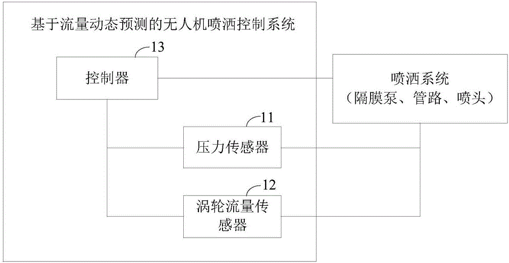
[0029] figure 1 It shows a schematic structural diagram of an unmanned aerial vehicle spraying control system based on flow dynamic prediction provided by an embodiment of the present invention, as shown in figure 1 As shown, the UAV spraying control system based on flow dynamic prediction in this embodiment includes: pressure sensor 11 and contr...


PUM


Abstract

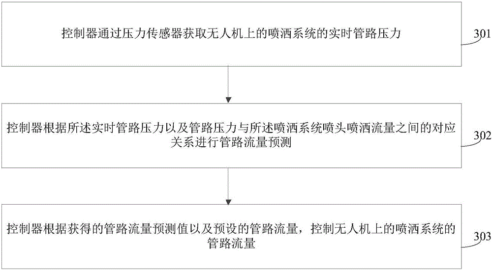
The invention provides an unmanned aerial vehicle spraying control system and method based on flow dynamic prediction. The system comprises a pressure sensor and a controller, wherein the pressure sensor is respectively connected with the controller and a spraying system on an unmanned aerial vehicle; the controller is connected with the spraying system on the unmanned aerial vehicle; the pressure sensor is used for obtaining a real-time pipeline pressure of the spraying system and transmitting the real-time pipeline pressure to the controller; and the controller is used for predicating pipeline flow according to the real-time pipeline pressure and a corresponding relation between the pipeline pressure and the nozzle spraying flow of the spraying system and also used for controlling the pipeline flow of the spraying system on the unmanned aerial vehicle according to the obtained pipeline flow predicated value and a preset pipeline flow. Through adoption of the system provided by the invention, the spraying amount of each acre of operation area can be accurately and dynamically controlled in the speed changing process and a situation of large spraying flow error caused by manual operation can be also avoided.

Description

technical field [0001] The invention relates to the technical field of aerial spraying operations, in particular to a spraying control system and method for drones based on flow dynamic prediction. Background technique [0002] Aerial spraying operations are an important means of modern agricultural plant protection operations. In the field of aerial pesticide application operations, precise pesticide application by drones is the future technological development trend. At present, the spraying system (including: small diaphragm pump, pipeline and pressure sprinkler) is usually installed on the plant protection drone. According to the condition of the crop, the spraying amount per mu is set, and the working voltage of the pump is set before the aircraft takes off. Determine the fixed pressure of the pipeline, so that the flow rate is constant. After the aircraft takes off, the remote control hand visually watches the drone fly to the operation area, then turns on the spray s...

Claims


Application Information

Patent Timeline
IPC IPC(8): B64D1/18B64D47/00
CPCB64D1/18B64D47/00
Inventor 徐旻陈立平张瑞瑞徐刚唐青侯佳健姜洪亮
Owner 北京市农林科学院智能装备技术研究中心
Learn More