Method for producing two-material sliding bearings

A sliding bearing, dual-material technology, applied in the direction of bearings, shafts and bearings, bearing components, etc., can solve the problems of expensive, low deposition rate, etc., and achieve adaptability, coating rate reduction, improved wear performance and friction performance Effect

Inactive Publication Date: 2018-10-02
MIBA SINTER AUSTRIA
View PDF6 Cites 0 Cited by
  • Summary
  • Abstract
  • Description
  • Claims
  • Application Information

AI Technical Summary

Problems solved by technology

However, the disadvantages in this case are the expensive method technology and the low achievable deposition rates, so that sputtered layers with low layer thicknesses are produced, as described, for example, in EP 0 692 674 A2

Method used


Image

  • Method for producing two-material sliding bearings
  • Method for producing two-material sliding bearings

Examples


preparation example Construction

[0041] Thanks to the production method described in more detail below, the sliding layer 3 can be produced in such a way that the majority of the particles of the sliding layer 3, preferably all the particles (ie the first and the second particles) have at most 1 μm, in particular between 0.1 μm and 1 μm and the sliding layer 3 has a Vickers hardness of less than 100HV (0.025), in particular between 40HV (0.025) and 80HV (0.025).

[0042] Maximum particle size is understood here to mean the largest diameter that individual particles have due to their irregular shape. However, individual particles may be slightly larger than 1 μm depending on the preparation, however at least 90%, especially at least 95% of all particles have a particle size of at most 1 μm and the remaining particles have a maximum particle size of 1.5 μm.

[0043] According to a preferred embodiment variant it is proposed that the particle size of the second particles is at most half the particle size of the ...

Embodiment

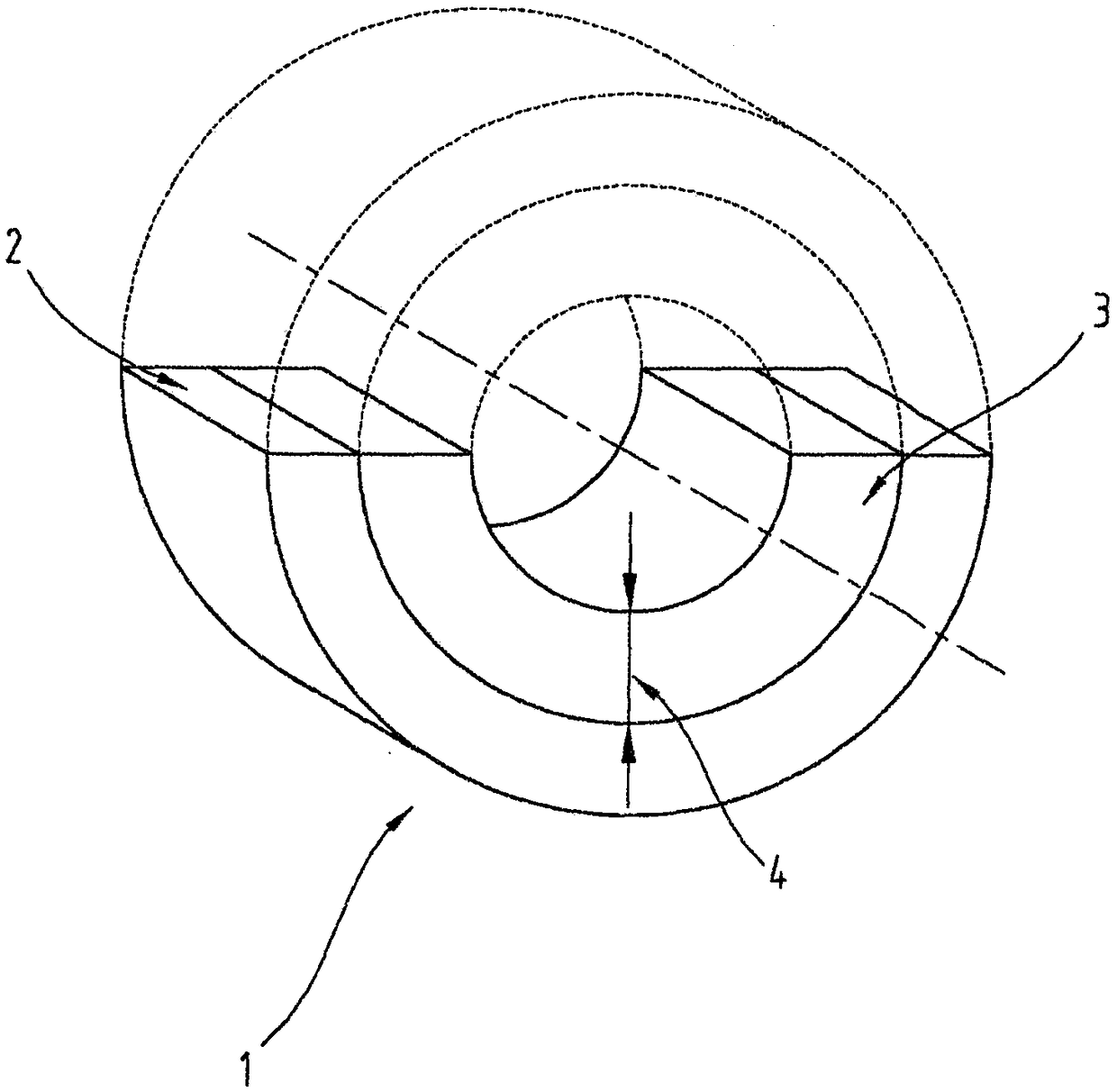
[0082] Within the scope of the present invention, a bimaterial plain bearing 1 is produced which has a sliding layer 3 composed of AlSn20Cu on a support layer 2 composed of steel.

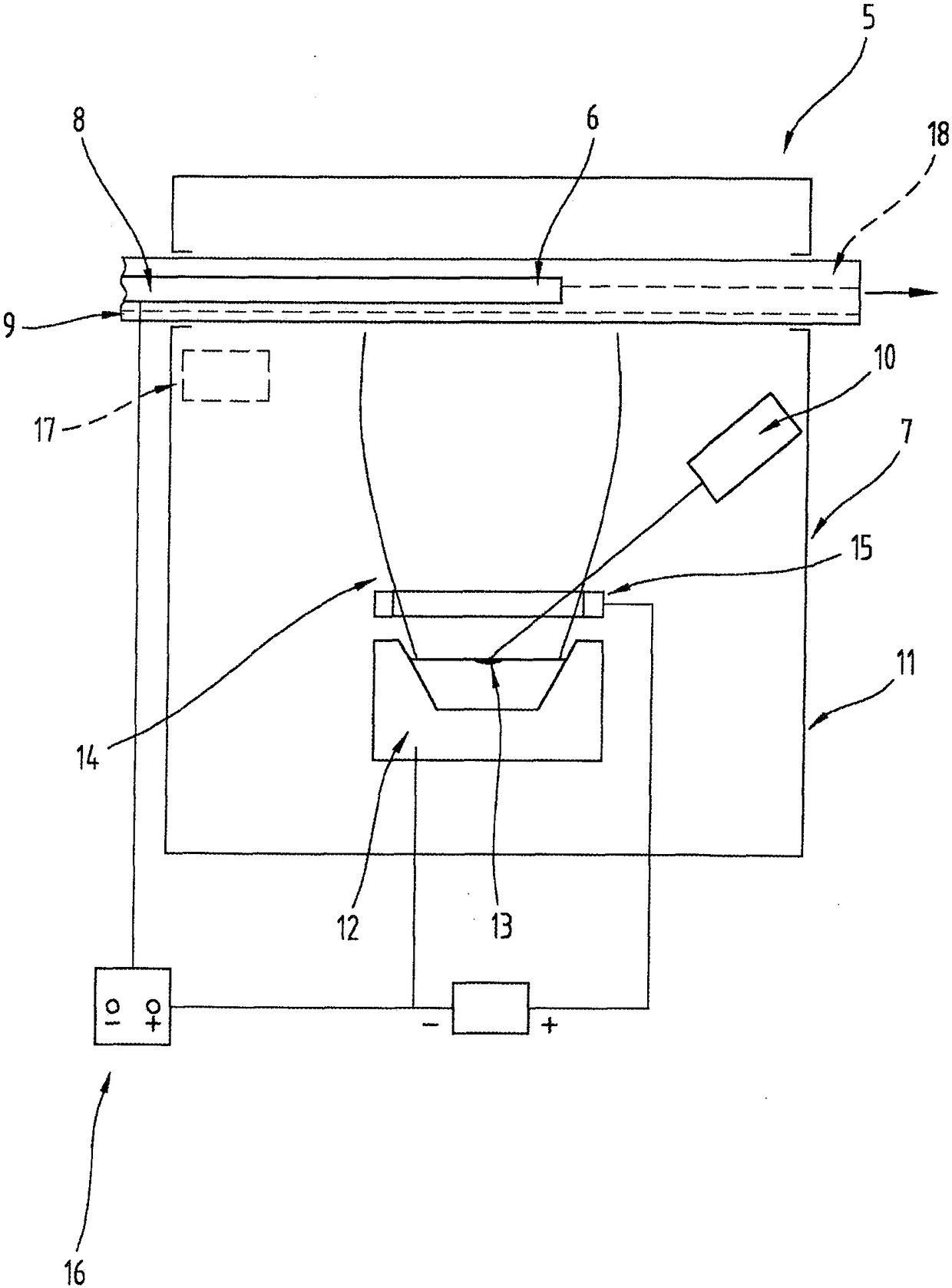
[0083] Pre-cleaning of steel substrates in plasma (p Ar ≈0.3Pa, P AEGD ≈3kW, U B ≈-1000V, t≈15 minutes).

[0084] With evaporation chamber 7 less than 2.10 -4 The initial pressure of Pa carries out the coating of the purified substrate 8 by using the AlSn14Cu5 alloy in the vessel 12 . The AlSn20Cu alloy is introduced into this vessel 12 during the deposition of the sliding layer 3. The distance between the substrate 8 and the container 12 was 300 mm. Substrate 8 in oil-cooled conveying device 9 (T 油,预备 =145°C) was transported through the evaporation chamber 7 . Use the following additional parameters for deposition:

[0085] Electron beam power: 100kW (thereby adjusting the surface temperature in the vessel 12 to about 1450°C)

[0086] Transport rate of substrate 8: 0.3mm / s

[0087] depos...


PUM

PropertyMeasurementUnit
thicknessaaaaaaaaaa
thicknessaaaaaaaaaa
Vickers hardnessaaaaaaaaaa

Abstract

The invention relates to a method for producing a bi-material sliding bearing (1) whereby a metal sliding layer (3) of at least two different particle types is deposited under reduced pressure from the gas phase on a flat, metal substrate (8), and a first particle type forms a matrix with first grains and the second particle type forms grains embedded in the matrix of the metal sliding layer (3), and the metal sliding layer (3) is produced with a thickness (4) of more than 250 μm and with a Vickers hardness below 100 HV(0.025), and the metal sliding layer (3) is made of a single layer in only one pass and with a maximum grain size of at most 1 μm for at least 90% of the first grains forming the matrix and with a maximum grain size for at least 90% of the embedded grains, and a maximum particle size of at most 1.5 μm for the remaining grains making up 100% of all grains.

Description

technical field [0001] The present invention relates to a method for producing a bimaterial plain bearing, according to which a metallic sliding layer composed of at least two different particle types is deposited from the vapor phase under reduced pressure on a flat metal substrate forming the support layer of the plain bearing. , wherein the particle type is produced by evaporation with at least one electron beam from at least one vessel forming the evaporation source, and the first particle type forms the matrix with the first particles and the second particle type forms the embedded matrix of the metal sliding layer Particles, and wherein the coated substrate is shaped into a plain bearing after deposition of a metallic sliding layer, wherein the metallic sliding layer is produced with a layer thickness of greater than 250 μm and with a Vickers hardness of less than 100 HV (0.025). [0002] The invention also relates to a bi-material sliding bearing comprising a metal supp...

Claims


Application Information

Patent Timeline
Patent Type & Authority Patents(China)
IPC IPC(8): F16C33/14C23C14/16C23C14/30
CPCF16C33/14C23C14/16C23C14/30C23C14/32F16C33/125F16C2202/04F16C2220/20F16C2223/30F16C2223/60F16C2240/60
Inventor W·耶特纳
Owner MIBA SINTER AUSTRIA
Why Eureka
Try Eureka