
Method and device for producing energy substance nitrous oxide by denitrification

A technology for nitrous oxide and energy production, which is applied in the direction of using microorganisms, enzymatic/microbiological devices, biomass post-treatment, etc., can solve the problems of slow reaction rate, achieve simple production process, and realize waste recycling Effect

Inactive Publication Date: 2016-10-26
SHENZHEN GRADUATE SCHOOL TSINGHUA UNIV
View PDF4 Cites 5 Cited by
  • Summary
  • Abstract
  • Description
  • Claims
  • Application Information

AI Technical Summary

Problems solved by technology

In addition, in foreign countries, carbon sources and nitrite are mainly added separately. First, carbon sources are added under anaerobic conditions to realize carbon accumulation as internal carbon sources, and then nitrite is added to achieve N 2 The production of O; the reaction rate is relatively slow, generally more than 20 hours

Method used


Image

  • Method and device for producing energy substance nitrous oxide by denitrification
  • Method and device for producing energy substance nitrous oxide by denitrification
  • Method and device for producing energy substance nitrous oxide by denitrification

Examples


experiment example 1

[0039] (1) Microbial domestication process

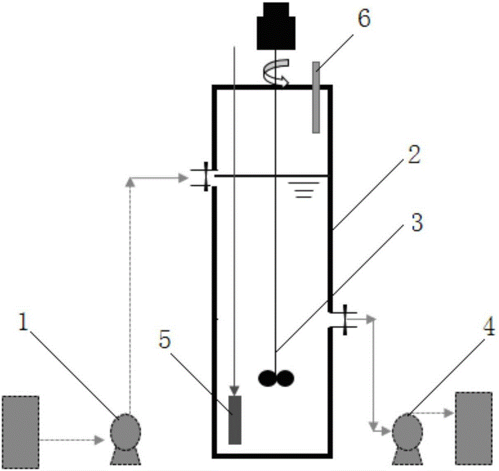
[0040] Two cylindrical plexiglass SBR reactors (sequencing batch reactors) with a height of 30 cm, a diameter of 10 cm, and an effective volume of 2000 mL were used to domesticate denitrifying bacteria. The operating cycle of the two SBR reactors is 4 hours, and the operating temperature is 26°C. 200mL of sludge is discharged every day, and the controlled sludge age (SRT) is 10 days. The SBR operation cycle includes 160min anoxic stirring (including 10min water inflow), 20min aerobic, 45min static sedimentation and 15min water outlet / idle. In each cycle, the water intake is 1L, the water output is 1L, and the hydraulic retention time (HRT) is 8h. The hydraulic retention time is the average residence time of sewage in the reactor. In this process, the reactor is 2L, and the water in and out is 1L in each cycle, so the residence time of sewage in the reactor is equivalent to two cycles, that is, 8h. The aerobic reaction stage is a...

experiment example 2

[0046] (1) Microbial domestication process

[0047] A cylindrical plexiglass SBR reactor with a height of 30 cm, a diameter of 10 cm, and an effective volume of 2000 mL was used to domesticate denitrifying bacteria. The operation cycle of the SBR reactor is 4h, and each cycle includes: 160min anoxic stirring (including 10min water inflow), 20min aerobic, 45min static settlement and 15min water outlet / idle. In each cycle, the water intake is 1L, the water output is 1L, and the hydraulic retention time (HRT) is 8h. Discharge 200mL of sludge at the aerobic end of a specific cycle every day, and control the sludge age (SRT) for 10 days. In the aerobic reaction stage, a microporous aerator was used for aeration, and the water inflow and drainage of the reactor was realized by controlling the opening and closing of the peristaltic pump by a timer, and the reactor was domesticated at 26°C for a long time. The influent carbon source of the reactor is glucose, and the influent COD co...


PUM


Abstract

The invention relates to a method and device for producing energy substance nitrous oxide by denitrification. The method uses a sequencing-batch denitrification fermentation reactor to produce nitrous oxide, and comprises the following steps: pumping sewage, which contains a carbon source, nitrate nitrogen and nutrient elements required by microbial growth, into the sludge-filled denitrification fermentation reactor by using a water inlet pump; carrying out anoxic fermentation reaction on the sludge-water mixed solution in the denitrification fermentation reactor to generate nitrous oxide; after reacting for preset time, blowing the generated nitrous oxide out of the denitrification fermentation reactor into a gas collecting system by a gas blowing process; and after the reaction finishes, stopping gas blowing, settling the sludge, and discharging a preset amount of the fermentation liquid. The method and device can enhance the nitrous oxide preparation efficiency and speed.

Description

technical field [0001] The invention relates to the technical field of sewage treatment, in particular to a method and a device for producing energy substance nitrous oxide through denitrification. Background technique [0002] Nitrogen is the fourth largest element in the earth's organisms, and its circulation in the earth's biochemical environment is an important earth's metabolic process. Denitrification is an important part of the nitrogen cycle. [0003] denitrifiers convert NO to 3 - sequentially reduced to NO 2 - , nitric oxide (NO), N 2 O, eventually completely reduced to nitrogen (N 2 ), as the pH value of the denitrification reaction gradually increased, the organic carbon source provided electrons for the reaction. During denitrification, N 2 O is an inevitable intermediate product when N 2 N is produced when O reductase is inhibited 2 O release. Some denitrifying bacteria themselves lack N 2 O reductase, denitrification can only be reduced to N 2 O t...

Claims


Application Information

Patent Timeline
IPC IPC(8): C12P3/00C12M1/107C12M1/04C12M1/02C12N1/36C02F3/28
CPCC02F3/282C02F2305/06C12M21/04C12M23/36C12M27/02C12M29/20C12N1/36C12P3/00
Inventor 吴光学苗甲赵英芬
Owner SHENZHEN GRADUATE SCHOOL TSINGHUA UNIV
Learn More