A spinning tube and its manufacturing method

A manufacturing method, technology of spinning tube, applied in the direction of manufacturing tools, metal rolling, metal rolling, etc., can solve the problem that the strength and wear resistance cannot meet the production requirements, affect the stability of production order, and the friction of spinning tube Large and other problems, to achieve the effect of reducing the friction coefficient, simple structure, and low cost

Active Publication Date: 2018-03-16
ZHEJIANG PENGCHENG TECH
View PDF4 Cites 0 Cited by
  • Summary
  • Abstract
  • Description
  • Claims
  • Application Information

AI Technical Summary

Problems solved by technology

[0003] At present, 9Cr1Mo materials are widely used in China to produce spinning tubes. During the high temperature (700-950°C) and high-speed (140m / s) wire rolling process, the strength and wear resistance often cannot meet the production requirements, and the service life is short. At the same time, due to the rapid change of the curvature of the entrance section of the spinning tube, the friction force of the first strong bending section of the spinning tube head (introduction section 300-500mm) is relatively large, which is easy to cause obvious scratches, and often occurs due to the wear of the spinning tube. The unplanned downtime and maintenance caused by perforation and perforation have seriously affected the stability of production order

Method used


Image

  • A spinning tube and its manufacturing method

Examples


Embodiment 1

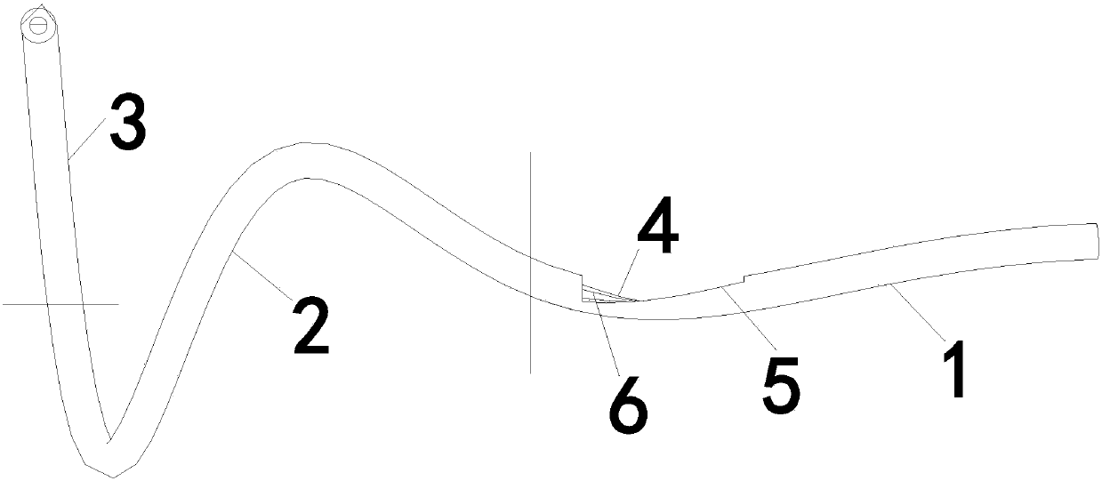
[0035] Such as figure 1 As shown, a spinning tube includes the following components by mass ratio: C: 0.06, Mn: 0.30, P≤0.02, S≤0.01, Si: 0.20, Cr: 7.50, Mo: 0.90, V: 0.18, Nb : 0.06, N: 0.03, Ni: ≤0.10, Cu: 0.10~0.30, W: ≤0.0004, Co: ≤0.001, B: 0.01~0.05, TiC≤0.0006, and the balance is iron.

[0036]The spinning tube in this embodiment includes an introduction section, a deformation section and a stabilization section. Grooves are made on the non-stressed side of the introduction section 300-500 mm, and a plasma arc driven by direct current is used as a heat source to melt tungsten carbide powder and spray it on the A tungsten carbide coating is formed on the stressed side; the thickness of the tungsten carbide coating is 0.05mm; TiC is nanoscale powder.

[0037] The manufacturing method of above-mentioned spinneret tube, comprises the following steps:

[0038] (1) Preparation of raw materials: The following components are taken according to the mass ratio: C: 0.06, Mn: 0.3...

Embodiment 2

[0050] A spinneret, comprising the following components by mass ratio: C: 0.07, Mn: 0.4, P≤0.02, S≤0.01, Si: 0.35, Cr: 820, Mo: 1.00, V: 0.20, Nb: 0.07, N: 0.05, Ni: ≤0.10, Cu: 0.10-0.30, W: ≤0.0004, Co: ≤0.001, B: 0.01-0.05, TiC ≤0.0006, and the balance is iron.

[0051] The spinneret in this embodiment includes an introduction section, a deformation section and a stabilization section. Grooves are made on the non-stressed side of the 400 mm area of ​​the introduction section, and a plasma arc driven by direct current is used as a heat source to melt tungsten carbide powder and spray it at a high speed until the force is applied. The tungsten carbide coating is formed on the side; the thickness of the tungsten carbide coating is 0.07mm; TiC is nano-scale powder.

[0052] The manufacturing method of above-mentioned spinneret tube, comprises the following steps:

[0053] (1) Preparation of raw materials: The following components are taken according to the mass ratio: C: 0.07, ...

Embodiment 3

[0065] A spinneret, comprising the following components by mass ratio: C: 0.10, Mn: 0.60, P≤0.02, S≤0.01, Si: 0.50, Cr: 9.20, Mo: 1.15, V: 0.25, Nb: 0.10, N: 0.07, Ni: ≤ 0.10, Cu: 0.10-0.30, W: ≤ 0.0004, Co: ≤ 0.001, B: 0.01-0.05, TiC ≤ 0.0006, and the balance is iron.

[0066] The spinneret of this embodiment includes an introduction section, a deformation section and a stabilization section. Grooves are made on the non-stressed side of the 500 mm area of ​​the introduction section, and a plasma arc driven by direct current is used as a heat source to melt tungsten carbide powder and spray it on the stressed side at high speed to form Tungsten carbide coating; the thickness of tungsten carbide coating is 0.09mm; TiC is nano-scale powder.

[0067] The manufacturing method of above-mentioned spinneret tube, comprises the following steps:

[0068] (1) Preparation of raw materials: C: 0.10, Mn: 0.60, P≤0.02, S≤0.01, Si: 0.50, Cr: 9.20, Mo: 1.15, V: 0.25, Nb: 0.10, N: 0.07, Ni: ...


PUM

PropertyMeasurementUnit
thicknessaaaaaaaaaa
thicknessaaaaaaaaaa
thicknessaaaaaaaaaa

Abstract

The invention discloses a spinning tube which comprises the following components by mass ratio: 0.06-0.10% of C, 0.30-0.60% of Mn, less than or equal to 0.02% of P, less than or equal to 0.01% of S, 0.20-0.50% of Si, 7.50-9.20% of Cr, 0.90-1.15% of Mo, 0.18-0.25% of V, 0.06-0.10% of Nb, 0.03-0.07% of N, less than or equal to 0.10% of Ni, 0.10-0.30% of Cu, less than or equal to 0.0004% of W, less than or equal to 0.001% of Co, 0.01-0.05% of B, 0.0006% of TiC, and the balance Fe. The invention further discloses a manufacturing method of the spinning tube. The spinning tube has the characteristics of simple structure, low cost, good abrasion resistance, high smooth finish, abrasion perforation prevention, long service life, and the like.

Description

technical field [0001] The invention relates to the production technology of a spinning tube, in particular to a spinning tube and a manufacturing method thereof. Background technique [0002] The laying head is the key equipment on the high-speed wire rod finishing mill production line, located between the water cooling section of the finishing mill's post-control cooling line and the loose coil conveyor. As one of the most important parts of the laying machine, the wire is changed from a linear motion to a spiral motion under the comprehensive action of the driving force, relative inertia force, friction force, and positive pressure caused by the pinch rod and the laying machine. , to form a stable coil with a diameter of about Ф1080mm, which is ejected from the spinning tube and evenly laid on the entrance channel of the Stelmore line. The spinneret is the key to control the transformation of the wire rod from a straight line to a wire rod. The production speed of the hi...

Claims


Application Information

Patent Timeline
Patent Type & Authority Patents(China)
IPC IPC(8): C22C38/02C22C38/04C22C38/22C22C38/24C22C38/26C22C38/16C22C38/32C22C38/54C22C38/42C22C38/44C22C38/46C22C38/48C23C4/10C23C4/134C23C4/131B21B41/00
CPCB21B41/00C22C38/001C22C38/02C22C38/04C22C38/16C22C38/22C22C38/24C22C38/26C22C38/32C22C38/42C22C38/44C22C38/46C22C38/48C22C38/54C23C4/10
Inventor 古宝庭何耀耀王超颖王永跃
Owner ZHEJIANG PENGCHENG TECH
Why Eureka
Try Eureka