
Purification equipment for sewage and waste gas in copper industry

A technology for purifying equipment and sewage, applied in biological water/sewage treatment, water/sludge/sewage treatment, gas treatment, etc. strong effect

Active Publication Date: 2018-07-24
广西东兴市富佳五金皮具有限公司
View PDF3 Cites 0 Cited by
  • Summary
  • Abstract
  • Description
  • Claims
  • Application Information

AI Technical Summary

Problems solved by technology

[0003] The sewage generated by the copper industry includes cooling water and electrolytic waste liquid, which are recycled and not discharged outside. However, domestic sewage, site flushing water, production sewage, and rainwater in contact with raw materials need to be discharged externally. This type of sewage contains heavy metals and suspended solids etc. The conventional treatment of copper industrial sewage requires a lot of investment, and the effect is not good

Method used


Image

  • Purification equipment for sewage and waste gas in copper industry
  • Purification equipment for sewage and waste gas in copper industry

Examples


Embodiment 1

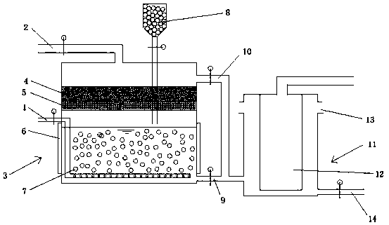
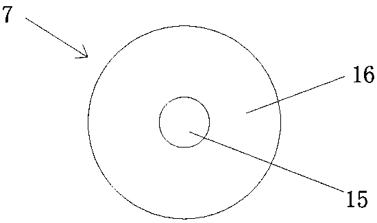
[0017] see Figure 1-2 , the present invention provides a technical solution: purification equipment for sewage and waste gas in the copper industry, comprising an inlet pipe 1, a water inlet pipe 2, a treatment box 3, an outlet pipe 9, an air outlet pipe 10 and a membrane pool 11; the inlet pipe 1 is arranged in the treatment box 3 At the bottom, a plurality of small holes are set on the air inlet pipe 1; the water inlet pipe 2 is connected to the treatment box 3 and is located on the top of the treatment box 3; the interior of the treatment box 3 includes three layers, from top to bottom are the heavy metal adsorption layer 4 and the SDG adsorbent layer 5 and purification layer, the heavy metal adsorption layer 4 and the SDG adsorbent layer 5 are located at the top of the treatment box 3, because a steel mesh is arranged at the bottom of the SDG adsorbent layer 5, and the steel mesh can fix the SDG adsorbent layer 5 while also allowing the Exhaust gas and sewage pass through...

Embodiment 2

[0022] see Figure 1-2 , the present invention provides a technical solution: purification equipment for sewage and waste gas in the copper industry, comprising an inlet pipe 1, a water inlet pipe 2, a treatment box 3, an outlet pipe 9, an air outlet pipe 10 and a membrane pool 11; the inlet pipe 1 is arranged in the treatment box 3 At the bottom, a plurality of small holes are set on the air inlet pipe 1; the water inlet pipe 2 is connected to the treatment box 3 and is located on the top of the treatment box 3; the interior of the treatment box 3 includes three layers, from top to bottom are the heavy metal adsorption layer 4 and the SDG adsorbent layer 5 and purification layer, the heavy metal adsorption layer 4 and the SDG adsorbent layer 5 are located at the top of the treatment box 3, because a steel mesh is arranged at the bottom of the SDG adsorbent layer 5, and the steel mesh can fix the SDG adsorbent layer 5 while also allowing the Exhaust gas and sewage pass through...

Embodiment 3

[0027] see Figure 1-2 , the present invention provides a technical solution: purification equipment for sewage and waste gas in the copper industry, comprising an inlet pipe 1, a water inlet pipe 2, a treatment box 3, an outlet pipe 9, an air outlet pipe 10 and a membrane pool 11; the inlet pipe 1 is arranged in the treatment box 3 At the bottom, a plurality of small holes are set on the air inlet pipe 1; the water inlet pipe 2 is connected to the treatment box 3 and is located on the top of the treatment box 3; the interior of the treatment box 3 includes three layers, from top to bottom are the heavy metal adsorption layer 4 and the SDG adsorbent layer 5 and purification layer, the heavy metal adsorption layer 4 and the SDG adsorbent layer 5 are located at the top of the treatment box 3, because a steel mesh is arranged at the bottom of the SDG adsorbent layer 5, and the steel mesh can fix the SDG adsorbent layer 5 while also allowing the Exhaust gas and sewage pass through...


PUM


Abstract

The invention discloses a purifying device for copper-industry wastewater and waste gas. The purifying device comprises a gas inlet pipe, a water inlet pipe, a treating box, a water outlet pipe, a gas outlet pipe and a film pool. The inside of the treating box sequentially comprises a heavy metal adsorption layer, an SDG adsorbent layer and a purifying layer from top to bottom, and the purifying layer comprises immobilized microorganism balls; a magnetic field generator is arranged outside the treating box; in the purifying device for copper-industry wastewater and waste gas, the purified wastewater and waste gas are mixed and enter the film pool, wastewater can be purified through a film assembly in the film pool, film pollution can be prevented through scouring of waste gas, the proportion of wastewater to waste gas ranges from 1:2.5 to 1:2, and the effect of the a waste-gas scouring film assembly is best; nitrogen oxide and particulate matter in wastewater and nitrogen oxide and particulate matter in waste gas can be removed through the immobilized microorganism balls; heavy metal matter can be removed through the heavy metal adsorption layer arranged in the treating box, and sulfuric acid mist can be removed through the SDG adsorbent layer.

Description

technical field [0001] The invention relates to the field of treatment of sewage and waste gas in the copper industry, in particular to purification equipment for sewage and waste gas in the copper industry. Background technique [0002] my country is a big country in copper production, but compared with other developed countries, the entire industry structure is unreasonable, and the development of the recycled copper industry lags behind. The development of recycled copper industry can solve the crisis of my country's copper industry, which is in line with the development trend of the copper industry in the world today, and meets the needs of my country's sustainable development and scientific development concept related policies. Therefore, the structure of my country's copper industry urgently needs to increase the development ratio of recycled copper industry. According to the current environmental status of my country's scrap copper enterprises, the main pollutant that...

Claims


Application Information

Patent Timeline
Patent Type & Authority Patents(China)
IPC IPC(8): B01D53/50B01D53/68B01D53/84C02F3/00C02F103/16
CPCB01D53/04B01D53/50B01D53/68B01D53/84B01D2251/95B01D2257/2064C02F3/00C02F2103/16Y02A50/20
Inventor 汪枫崔晓辉
Owner 广西东兴市富佳五金皮具有限公司
Learn More