Ordered nanostructure membrane electrode and preparation method thereof
A nanostructure, membrane electrode technology, applied in the direction of nanotechnology, nanotechnology, battery electrodes, etc., can solve the problems of low power density, low catalyst utilization rate, low electrochemical reaction activity of methanol, etc., and achieve the effect of improving catalytic activity
- Summary
- Abstract
- Description
- Claims
- Application Information
AI Technical Summary
Problems solved by technology
Method used
Image

Examples
preparation example Construction
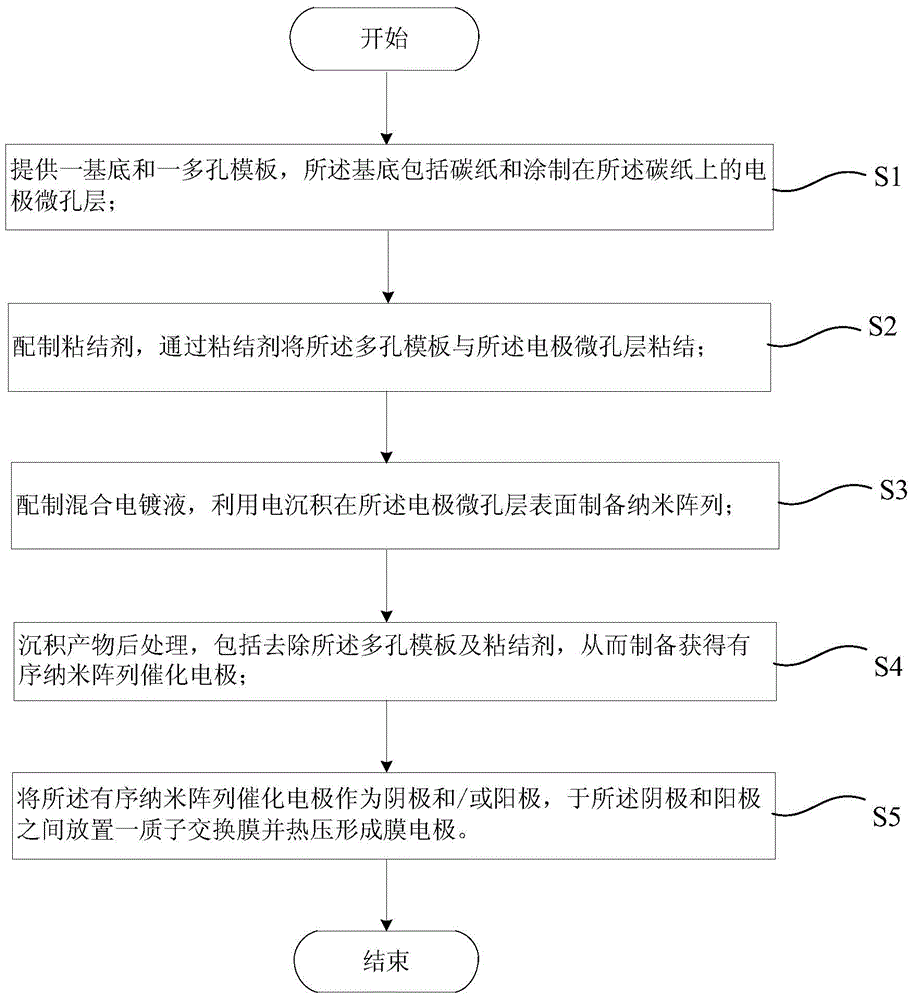
[0051] like figure 1 As shown, the present invention provides a method for preparing an ordered nanostructured membrane electrode applied to a fuel cell, and the method for preparing an ordered nanostructured membrane electrode at least includes the following steps:
[0052] S1, providing a substrate and a porous template, the substrate comprising carbon paper and an electrode microporous layer coated on the carbon paper;
[0053] S2, preparing a binder, and bonding the porous template to the electrode microporous layer through the binder;
[0054] S3, preparing a mixed electroplating solution, and preparing a nano-array on the surface of the electrode microporous layer by electrodeposition;
[0055] S4, post-processing the deposition product, including removing the porous template and the binder, thereby preparing an ordered nano-array catalytic electrode;
[0056] S5, using the ordered nano-array catalytic electrode as a cathode and / or an anode, placing a proton exchange m...
Embodiment 1
[0076] This embodiment provides a method for preparing an ordered platinum nanowire film electrode, comprising the following steps:
[0077] Weighing 20.0mg of carbon nanotubes, 40.4mg of mass fraction of 12.39% polytetrafluoroethylene (PTFE) solution, 200mg of isopropanol (IPA) aqueous solution (IPA:H 2 O=1:1), and after mixing it, sonicate for 120min; use a spatula to smear on carbon paper containing 20% PTFE with a mass fraction of 2.0mg·cm -2 carbon nanotubes; and then sintering at a temperature of 350° C. for 30 minutes to obtain a cathode microporous layer.
[0078] Weigh polyvinylidene fluoride (PVDF) and N-methylpyrrolidone (NMP) to prepare a mixed solution with a mass fraction of PVDF of 8.14%; magnetically stir at 25° C. for 8 hours to obtain a PVDF solution as a binder.
[0079] The PVDF solution that draws about 50.0mg is coated on the described cathode microporous layer and is scraped off with a scraper so that about 32.0mg of PVDF solution is coated on the mic...
Embodiment 2
[0091] This embodiment provides a method for preparing an ordered platinum nanotube membrane electrode, comprising the following steps:
[0092] Weighing 60.0mg of carbon nanotubes, 179.2mg of 8.37% PTFE solution, 600mg of IPA aqueous solution (IPA:H 2 O=1:1), and after mixing it, sonicate for 120min; use a spatula to smear on carbon paper containing 20% PTFE with a mass fraction of 2.0mg·cm -2 carbon nanotubes; and then sintering at a temperature of 350° C. for 30 minutes to obtain a cathode microporous layer.
[0093] PVDF and NMP were weighed, and a mixed solution with a mass fraction of PVDF of 5.28% was prepared; magnetically stirred at 25° C. for 8 hours to obtain a PVDF solution as a binder.
[0094] Draw about 50 mg of PVDF solution and apply it on the cathode microporous layer and scrape it flat with a scraper so that about 32 mg of PVDF solution is applied on the microporous layer, and then bond an AAO template with a double-pass aperture of 200 nm on the cathode ...
PUM
| Property | Measurement | Unit |
|---|---|---|
| Diameter | aaaaa | aaaaa |
Abstract
Description
Claims
Application Information
 - Generate Ideas
- Intellectual Property
- Life Sciences
- Materials
- Tech Scout
- Unparalleled Data Quality
- Higher Quality Content
- 60% Fewer Hallucinations
Browse by: Latest US Patents, China's latest patents, Technical Efficacy Thesaurus, Application Domain, Technology Topic, Popular Technical Reports.
© 2025 PatSnap. All rights reserved.Legal|Privacy policy|Modern Slavery Act Transparency Statement|Sitemap|About US| Contact US: help@patsnap.com