Comparator and relaxation oscillator

A relaxation oscillator and comparator technology, applied in the direction of pulse processing, pulse generation, electrical components, etc., can solve the problem of low current utilization rate, achieve the effects of reducing power consumption, improving current utilization rate, and reducing production costs

Active Publication Date: 2016-11-23
ALLWINNER TECH CO LTD
View PDF7 Cites 13 Cited by
  • Summary
  • Abstract
  • Description
  • Claims
  • Application Information

AI Technical Summary

Problems solved by technology

Therefore, at any moment, the current consumed by the main circuit of the oscillator on the capacitor is twice the charging current of the capacitor, and the current utilization rate is low.

Method used


Image

  • Comparator and relaxation oscillator
  • Comparator and relaxation oscillator
  • Comparator and relaxation oscillator

Examples


no. 1 example

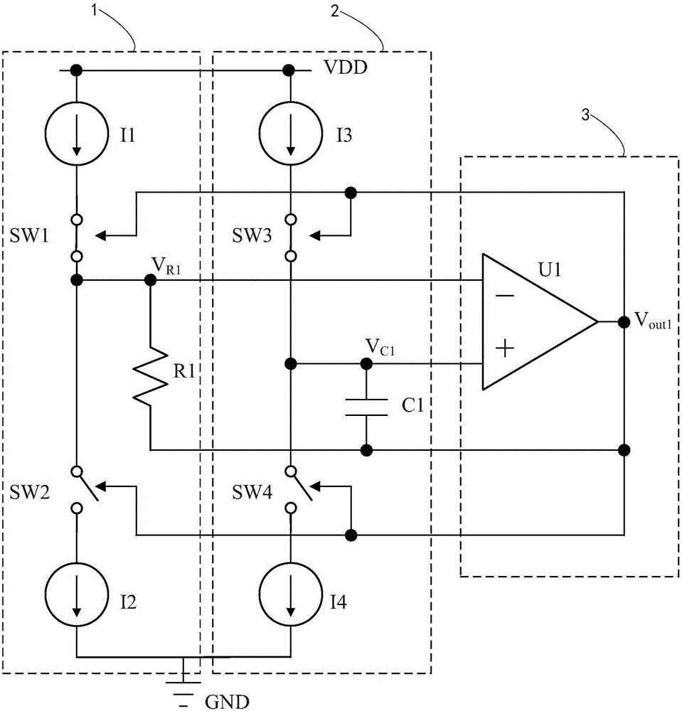
[0034] like figure 1 as shown, figure 1It is an electrical schematic diagram of a relaxation oscillator circuit of an embodiment of the relaxation oscillator of the present invention. It can be seen from the figure that the relaxation oscillator circuit of the oscillator includes a threshold voltage generating circuit 1, a capacitor charging and discharging circuit 2, and a comparator circuit 3. The threshold voltage generating circuit 1 inputs a threshold value to the inverting input terminal of the comparator circuit 3. The capacitor charging and discharging circuit 2 inputs the capacitor voltage signal to the non-inverting input terminal of the comparator circuit 3 . Threshold voltage generating circuit 1 includes a first current source I1, a second current source I2 and a threshold resistor R1, the first current source I1 applies a current to the threshold resistor R1 through a first inverting switching element SW1 (that is, the current flows from the first current source...

no. 2 example

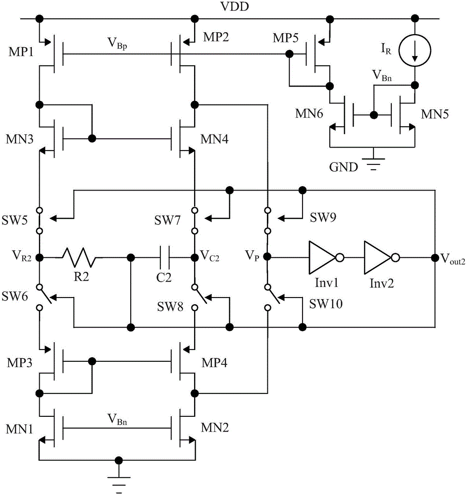
[0042] like figure 2 as shown, figure 2 It is a schematic circuit diagram of another embodiment of the present invention. In this embodiment, the relaxation oscillator circuit includes a bias circuit, and the bias circuit includes a reference current source I R , the fifth NMOS transistor MN5, the sixth NMOS transistor MN6 and the fifth PMOS transistor MP5, wherein the reference current source I R electrically connected to the power line VDD while referenced to the current source I R It is electrically connected to the drain and gate of the fifth NMOS transistor MN5, the gate of the fifth NMOS transistor MN5 is electrically connected to the gate of the sixth NMOS transistor MN6, and the drain and gate of the fifth PMOS transistor MP5 are connected to the sixth NMOS transistor MN5. The drain of the tube MN6 is electrically connected. The bias circuit consists of a current source I R , the fifth NMOS transistor MN5 , the sixth NMOS transistor MN6 and the fifth PMOS transi...

Embodiment 3

[0050] see Figure 4 , Figure 4 It is the electrical principle diagram of the relaxation oscillator circuit of the third embodiment of the relaxation oscillator of the present invention.

[0051] In this embodiment, the relaxation oscillator circuit includes a bias circuit, and the bias circuit includes a reference current source I R1 , NMOS tube MN51, NMOS tube MN61 and PMOS tube MP51, wherein the reference current source I R1 electrically connected to the power line VDD while referenced to the current source I R1 It is electrically connected to the drain and gate of NMOS transistor MN51, the gate of NMOS transistor MN51 is electrically connected to the gate of NMOS transistor MN61, and the drain and gate of PMOS transistor MP51 are electrically connected to the drain of NMOS transistor MN61. The bias circuit consists of a current source I R1 , NMOS tube MN51, NMOS tube MN61 and PMOS tube MP51 form a mirror current source to provide bias current for the oscillation circu...


PUM


Abstract

The invention provides a comparator and a relaxation oscillator. The comparator comprises a comparator circuit including a current mode comparator circuit; and the current mode comparator circuit consists of a first current mode comparator circuit and a second current mode comparator circuit, wherein the first current mode comparator circuit and the second current mode comparator circuit are connected with a first input terminal and a second input terminal of the comparator circuit electrically. The first current mode comparator circuit includes two N type MOS tubes and grids of the two N type MOS tubes are connected electrically; and the second current mode comparator circuit includes two P type MOS tubes and grids of the two P type MOS tubes are connected electrically. The oscillator includes the comparator. According to the invention, the production cost can be lowered; the development period can be shortened; the frequency stability is improved; and the ultra-low power consumption is realized.

Description

technical field [0001] The invention relates to the field of oscillators, in particular to a comparator used in oscillators and a relaxation oscillator based on bootstrap technology using the comparator. Background technique [0002] All monolithic integrated circuit devices that require clock signals need clock sources to provide clock signals. The mainstream clock sources include off-chip crystal oscillators, on-chip harmonic oscillators, on-chip ring oscillators and on-chip relaxation oscillators. Crystal oscillators are because of their Good frequency accuracy and stability are widely used. With the development of Internet of Things devices, wearable devices and medical implantable devices, the market has higher and higher requirements for the integration of electronic devices, stricter requirements for power consumption control, and stronger desire for cost reduction. , so the performance of the on-chip oscillator needs to be greatly improved to replace the crystal osc...

Claims


Application Information

Patent Timeline
Patent Type & Authority Applications(China)
IPC IPC(8): H03K3/012H03K5/24
CPCH03K3/012H03K5/2472H03K3/0231H03K4/50
Inventor 樊骕研
Owner ALLWINNER TECH CO LTD
Why Eureka
Try Eureka