Novel ship monitoring magnetic field sensor

A magnetic field sensor and sensor technology, applied in the size/direction of the magnetic field, the use of electromagnetic devices for magnetic field measurement, instruments, etc., can solve the problems of difficult manufacturing of superconducting Josephson junctions, large influence of magnetic field gradients, and complex system structure, etc. Achieve the effect of superior recognition ability, high concealment and small size

Active Publication Date: 2016-12-07
CHONGQING UNIV
View PDF6 Cites 3 Cited by
  • Summary
  • Abstract
  • Description
  • Claims
  • Application Information

AI Technical Summary

Problems solved by technology

[0006] (2) The proton precession magnetometer is developed based on the principle of magnetic resonance by using the precession phenomenon of protons in the geomagnetic field. Its advantages are high precision, generally in the range of 0.1-10nT, good stability, and high working speed. Fast, can directly read the nT value of the geomagnetic field. The disadvantage is that the polarization power is high, and it can only be used for fast point measurement, and it is greatly affected by the magnetic field gradient.
[0007] (3) The optical pump magnetometer is a magnetometer made according to the atomic transition principle in the nucleus. It has high sensitivity, can reach 0.001nT, no zero drift, no orientation, no strict requirements on the surrounding magnetic field gradient and continuous observation advantages, but its structure is relatively complex, and high-precision frequency measurement is required for detection
[0008] (4) The Superconducting Quantum Interference Magnetometer (SQUID) is manufactured according to the principle of superconductivity. It is by far the most sensitive instrument for measuring magnetic fields, with a sensitivity as high as 10-5~10-6nT. However, it is difficult to manufacture superconducting Josephson junctions.

Method used


Image

  • Novel ship monitoring magnetic field sensor
  • Novel ship monitoring magnetic field sensor
  • Novel ship monitoring magnetic field sensor

Examples


Embodiment Construction

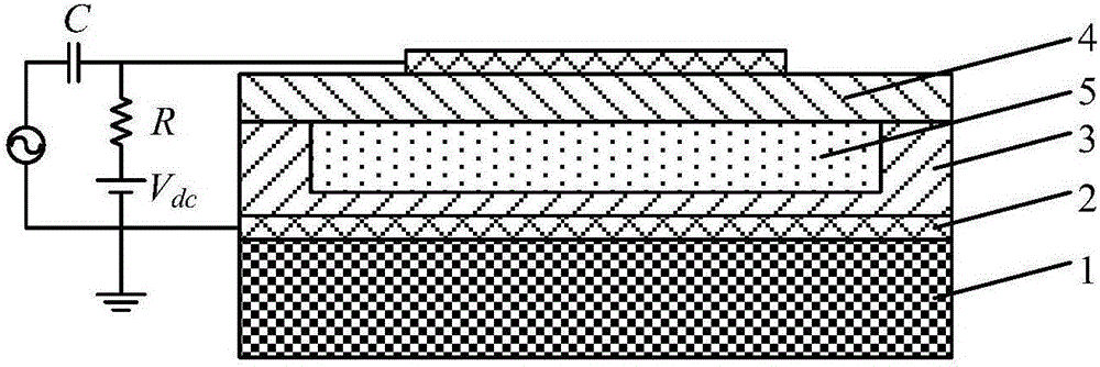
[0037] The present invention provides a new type of naval ship monitoring magnetic field sensor, which comprises a silicon substrate 1, a metal electrode 2, an insulating layer 3, a piezoelectric film 4 and a capacitor cavity 5 filled with magnetic liquid. The specific implementation method of the present invention will be described below in conjunction with the drawings and embodiments.

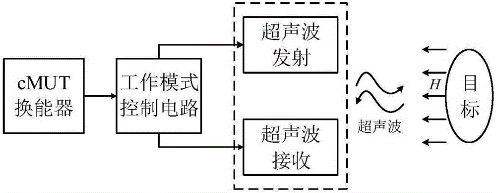
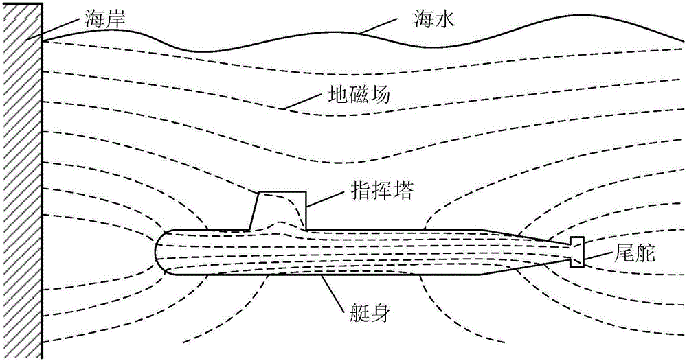
[0038] This embodiment provides a new type of ship monitoring magnetic field sensor, and its specific technical implementation ideas: use MEMS technology to design and manufacture a capacitive micro-machined ultrasonic transducer (cMUT) as an underwater acoustic transducer, in which the pair is injected into the capacitive cavity The magnetic field-sensitive low-concentration magnetic liquid is used as the ultrasonic transmission medium. In the absence of a magnetic anomaly source, the sensor works as an underwater acoustic transducer. When the submarine approaches the coast, it will cause magne...


PUM

PropertyMeasurementUnit
Thicknessaaaaaaaaaa
Viscosityaaaaaaaaaa

Abstract

The invention relates to a novel ship monitoring magnetic field sensor based on the ultrasonic sensing and magnetic detection technology. The sensor comprises a silicon substrate, a metal electrode, an insulating layer, a piezoelectric film, and a cavity filled with low concentration magnetic fluid. The sensor is characterized in that the sensor can emit or receive an ultrasonic wave, the viscosity of the magnetic fluid in the cavity is very sensitive to an external magnetic field, in the condition of no magnetic abnormal source, the sensor carries out ultrasonic detection in a mode of an underwater acoustic transducer, when a magnetic abnormal source appears, the sensor can carry out ultrasonic detection and magnetic detection at the same time, and the ultrasonic frequency emitted by the sensor can be controlled by applying a bias magnetic field. The ship monitoring magnetic field sensor is manufactured by using the advanced micro nano processing technology, the volume is small, the power consumption is low, the frequency band is wide, a one-dimensional line array (1D) and a two-dimensional surface array (2D) can be made, the sensor is compatible with a front-end electronic circuit, the mass production of devices is facilitated, and the sensor is suitable for coastal defense, anti submarine, warship detection, ocean topography detection and the like.

Description

Technical field [0001] The patent of the invention relates to the technical field of ultrasonic sensing and magnetic detection, in particular to a new type of ship monitoring magnetic field sensor, which is mainly used for coastal defense, anti-submarine and ship detection. Background technique [0002] The detection of large underwater targets (submarines, nuclear submarines, submerged reefs, etc.) can be achieved by means of sonar, radar, laser, and magnetic detection. Among them, sonar technology is the earliest adopted underwater detection technology, which is widely used in all aspects of naval underwater activities and is the main means of submarine detection, reconnaissance and navigation. As an important part of the sonar system, the underwater acoustic transducer is a device for mutual conversion of electrical energy and sound energy. Its principle is to use the propagation characteristics of sound waves in water to achieve electroacoustic energy conversion through piezo...

Claims


Application Information

Patent Timeline
IPC IPC(8): G01R33/06G01V3/08G01S15/06
CPCG01R33/06G01S15/06G01V3/081Y02A90/30
Inventor 刘玉菲孙长河姜森林代付康
Owner CHONGQING UNIV
Why Eureka
Try Eureka