
High-stability laser pumping source with overtemperature protection function

A technology with high stability and protection function, applied in the direction of lasers, laser components, laser monitoring devices, etc., can solve problems such as easy to burn out butterfly lasers, rising, unable to accurately and quickly keep up with changes in electrical signals, etc.

Active Publication Date: 2016-12-07
JILIN UNIV
View PDF3 Cites 19 Cited by
  • Summary
  • Abstract
  • Description
  • Claims
  • Application Information

AI Technical Summary

Problems solved by technology

[0003] In the fiber laser, a laser pump source must provide the energy source for the entire fiber laser. As the core part of the fiber laser, the main technical index of the pump source is the stability of the output laser. In various laser generating circuits , the system composed of a butterfly laser module, a current driver, and a temperature controller is widely used due to its advantages of convenient use, rich functions, high stability, and easy integration. In 2014, the invention patent "a high stability fiber laser pump source" was applied, the application number is 2014103102505. In this document, the butterfly laser module is used as the light source, and the constant current driver and the constant temperature controller with high stability are used. To drive and control the temperature, in addition to the temperature control of the butterfly laser module, the temperature control of other nuclear devices in the system is also carried out, which effectively improves the stability of the output laser, but this technology still has certain defects: 1. The driver adopts an ordinary linear proportional control method, and the butterfly laser module is an electro-optical conversion device. During the conversion process, the output optical signal and the input electrical signal will inevitably be delayed. When the power needs to be changed frequently, the output power will not be able to Accurately and quickly keep up with changes in electrical signals, or when changing the driving current, the output optical power will oscillate near the target power; Second, there is no over-temperature protection measure in the system, once the heat generated by the butterfly laser module exceeds the temperature controller When the temperature control capability of the laser is high or the temperature controller fails, the temperature of the laser will rise sharply, and it is easy to burn out the butterfly laser module

Method used


Image

  • High-stability laser pumping source with overtemperature protection function
  • High-stability laser pumping source with overtemperature protection function
  • High-stability laser pumping source with overtemperature protection function

Examples


Embodiment 1

[0034] Embodiment 1 Overall structure of the system

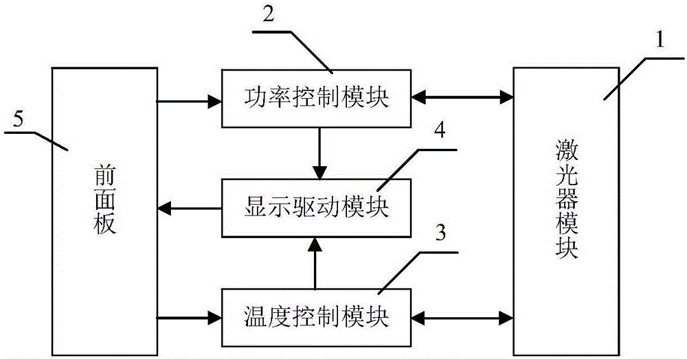
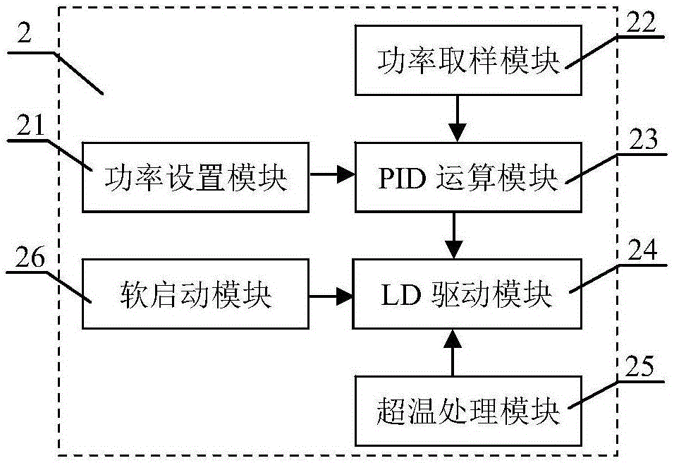
[0035] Such as figure 1 As shown, the system structure includes a laser module 1, a power control module 2, a temperature control module 3 and a display driver module 4, and the structure of the power control module 2 is as follows figure 2 As shown, it is composed of a power setting module 21, a power sampling module 22, a PID operation module 23, an LD drive module 24, an over-temperature processing module 25 and a soft-start module 26, and the power control module 2 and the temperature control module 3 are both connected to the laser module 1 Connected, the power control module 2 provides the drive current to the laser module 1, the size of the output optical power is controlled by the size of the drive current, the required power (output in voltage form) is set by the power setting module 21, and the power sampling module 22 passes through the laser module. The photodiode (PD) integrated in 1 samples the output optica...

Embodiment 2

[0036] Embodiment 2 laser module

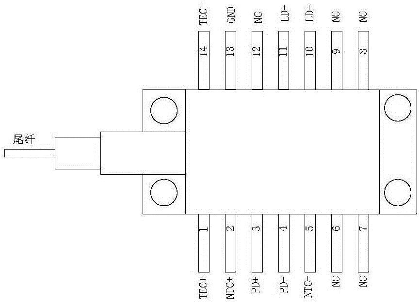
[0037] The laser module 1 of this embodiment selects the laser module of Jie Dixun LC96 butterfly package, and its package and pin schematic diagram are as follows image 3 As shown, the laser module integrates a laser diode LD, a photodiode PD, a thermoelectric cooler TEC, and a thermistor NTC. The pigtail is directly connected to the laser output port on the front panel 5 for outputting laser light. There are 14 in this module pins, of which pins 6, 7, 8, 9, and 12 are empty pins (NC), and pins 1 and 14 are the two current input terminals of the internal thermoelectric cooler (port TEC+ and port TEC -) It is used to connect with the current output port of the temperature control module 3. Pin 2 and pin 5 are two wiring ports (port NTC+ and port NTC-) of the internal integrated thermistor, which are used to connect with the thermal sensor of the temperature control module 3 The resistance input terminal is connected, and the port NTC+ is al...

Embodiment 3

[0038] Embodiment 3 temperature control module

[0039]The temperature control module 3 described in the present invention is a prior art, specifically, Chinese patent CN2007100559129 (high-stability constant temperature controller) or Chinese patent CN2010102701027 (wide power consumption limitation based on thermoelectric cooler) applied by the applicant's research group type constant temperature controller), the temperature control module 3 has a set of current output terminals for driving the thermoelectric cooler for cooling or heating, and the temperature control module 3 also has a set of thermistor input terminals for connecting the thermistor. And the resistance value change of the thermistor (the change in resistance value reflects the change in temperature) is converted into voltage change and fed back to the temperature control module 3 to realize automatic temperature control. The sliding rheostat used to adjust the working temperature in the temperature control mo...


PUM


Abstract

The invention discloses a high-stability laser pumping source with an overtemperature protection function and belongs to the technical field electronic equipment. The laser pumping source structurally comprises a laser module (1), a power control module (2) and a temperature control module (3). The laser pumping source is characterized by further comprising a display driving module (3) structurally, and the power control module (2) is composed of a power setting module (21), a power sampling module (22), a PID operation module (23), an LD driving module (24), an overtemperature processing module (25) and a soft starting module (26). The laser pumping source is high in stability and has the functions of overtemperature alarming power-off and soft starting.

Description

technical field [0001] The invention belongs to the technical field of electronic equipment, in particular to a high-stability laser pumping source device with an over-temperature protection function. Background technique [0002] With its low threshold, high power, high beam quality, good reliability, compact structure and good heat dissipation, fiber lasers are widely used in laser fiber communication, laser space long-distance communication, industrial shipbuilding, automobile manufacturing, laser engraving, Laser marking, laser cutting, printing roll, metal and non-metal drilling / cutting / welding (brazing, quenching, cladding and deep welding), military defense security, medical equipment and other fields. A fiber laser is a laser that uses a rare earth-doped fiber as a gain medium. Fiber lasers are developed on the basis of fiber amplifiers and are composed of three basic elements: pump source, rare earth element-doped fiber, and resonant cavity. The working principle i...

Claims


Application Information

Patent Timeline
IPC IPC(8): H01S3/09H01S3/13H01S3/00
CPCH01S3/0014H01S3/09H01S3/1305
Inventor 汝玉星田小建吴戈高博单江东高福斌李尚安明梁雪刘大恺马春阳
Owner JILIN UNIV
Learn More