Bias circuit for radio-frequency power amplifier, and implementation method thereof

A bias circuit, radio frequency power technology, applied in high-frequency amplifiers, amplifiers, differential amplifiers, etc., can solve the problem of very sensitive changes, and achieve the effect of reducing sensitivity and improving linearity

Active Publication Date: 2016-12-07
RDA MICROELECTRONICS SHANGHAICO LTD
View PDF5 Cites 10 Cited by
  • Summary
  • Abstract
  • Description
  • Claims
  • Application Information

AI Technical Summary

Problems solved by technology

This is impossible to achieve in practical applications, and only a partial proportion of temperature compensation can be achieved in practical applications
Second, this bias circuit is very sensitive to changes in the reference voltage Vreg

Method used


Image

  • Bias circuit for radio-frequency power amplifier, and implementation method thereof
  • Bias circuit for radio-frequency power amplifier, and implementation method thereof
  • Bias circuit for radio-frequency power amplifier, and implementation method thereof

Examples


Embodiment Construction

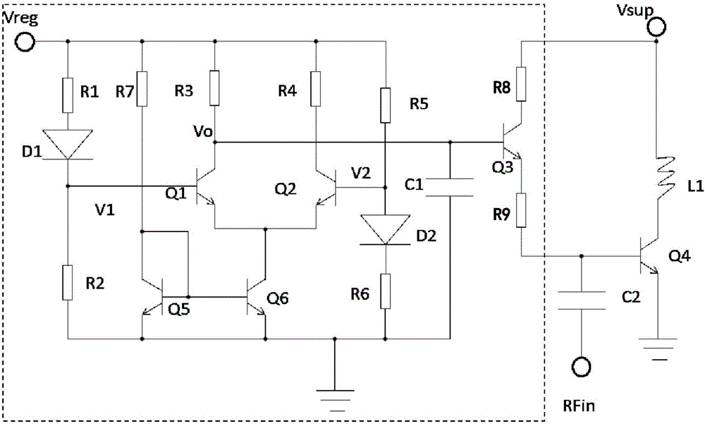
[0022] see figure 2 , which is Embodiment 1 of the radio frequency power amplifier and its bias circuit of the present application, where the dotted box part is the bias circuit. The RF power amplifier mainly includes a triode Q4, also called a power tube, its collector is connected to the power supply voltage Vsup through an inductor L1, its emitter is grounded, and its base is connected to the RF signal input terminal RFin through a capacitor C2. The collector of the power transistor Q4 is also used as a radio frequency signal output terminal (not shown). The bias circuit mainly includes five triodes and two diodes. The resistor R1, the diode D1 and the resistor R2 connected in series from the reference voltage Vreg to the ground form the first voltage dividing branch. The cathode of the diode D1 is called the bias point V1, which is used to provide the triode Q1 base bias voltage. Resistor 5 R5, diode 2 D2 and resistor 6 R6 connected in series from the reference voltage...


PUM


Abstract

The invention discloses a bias circuit for a radio-frequency power amplifier. The bias circuit comprises a differential amplifier composed of two audions; the differential amplifier is that the bases of the two audions are used as differential input ends and the collector of one audion is used as a single output end; the bias circuit further comprises an active driving tube; the base of the active driving tube receives voltage of the single output end of the differential amplifier as input; the emitter of the active driving tube provides base bias current for a power tube; two voltage dividing branches respectively provide base voltage for the two audions forming the differential amplifier; and furthermore, when the temperature is changed, the change directions of the base voltage of the two audions forming the differential amplifier are opposite. By means of the bias circuit disclosed by the invention, the sensitivity to temperature change can be obviously reduced; the linearity of the radio-frequency power amplifier is improved; and thus, the radio-frequency power amplifier can keep a normal working state in a relatively severe working condition and environment.

Description

technical field [0001] The present application relates to a bias circuit of a radio frequency power amplifier. Background technique [0002] In the radio frequency receiving circuit, the radio frequency front end (RF front end) usually refers to all circuits between the antenna and the mixer, which are used to convert the radio frequency signal received by the antenna into a lower frequency intermediate frequency signal. Taking a receiver with a superheterodyne structure as an example, the RF front-end usually includes a bandpass filter, an RF power amplifier, a local oscillator, a mixer, and possibly an analog-to-digital converter. [0003] In the RF front-end circuit, the RF power amplifier is one of the most important devices and also the device that consumes the most energy. During operation, the RF power amplifier will generate a lot of heat, and its temperature will rise accordingly. Due to the PN junction characteristics, the forward current increases with temperatu...

Claims


Application Information

Patent Timeline
Patent Type & Authority Applications(China)
IPC IPC(8): H03F1/30H03F1/32H03F3/19H03F3/45
CPCH03F1/30H03F1/3211H03F3/19H03F3/4508
Inventor 柯庆福林甲富孙凯郑新年
Owner RDA MICROELECTRONICS SHANGHAICO LTD
Why Eureka
Try Eureka