Internal combustion engine exhaust utilizing thermal energy power system based on semiconductor condensation
A power system and internal combustion engine technology, applied in the direction of machines/engines, generators/motors, electrical components, etc., can solve the problems of large waste of heat energy, small external waste heat absorption rate, unstable gasification temperature of working fluid, etc., and achieve stable gas Temperature and flow rate of working fluid, improve gasification efficiency and condensation efficiency, avoid the effect of unstable turbine speed
- Summary
- Abstract
- Description
- Claims
- Application Information
AI Technical Summary
Problems solved by technology
Method used
Image
Examples
Embodiment 1
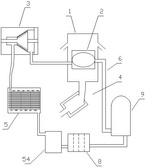
[0082] Embodiment one (such as figure 1 Shown): a power system based on semiconductor condensation for utilizing heat energy from internal combustion engine exhaust, including a heat collector 1, a gasification device 2, a turbine 3, an internal combustion engine exhaust pipe 4, a condensing device 5, a circulation pipeline 6, a circulation medium 7 and a unit The hydraulic pump 9, the gasification device 2, the turbine 3, the condensing device 5 and the one-way hydraulic pump 9 realize circulation through the circulation pipeline 6 in sequence. The circulation pipeline 6 contains a circulating working medium 7, and the heat collection device 1 is installed 2 outside, used for gasification heating of working fluid in gasification device 2;
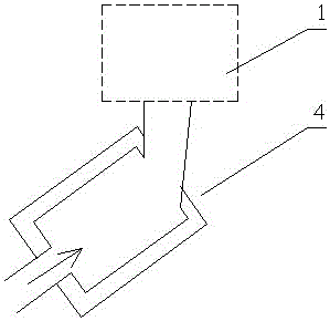
[0083] (Such as figure 2 As shown) the exhaust pipe 4 of the internal combustion engine is connected to the heat collector 1;
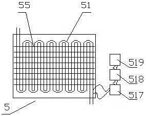
[0084] (Such as image 3 As shown), the condensation device 5 includes a condensation pipe 51 and a heat di...
Embodiment 2
[0094] Embodiment two (such as Figure 6 Shown): The difference from Embodiment 1 is that the heat collecting device 1 includes an upper cover 11 and a lower cover 12, a heating port 13 is provided in the middle of the lower cover 12, and the upper cover 11 and the lower cover 12 are respectively located on the upper and lower sides. Between 11 and the lower cover 12 is a heat collecting chamber 14, two layers of upper cover protruding rings 111 are distributed on the lower part of the upper cover 11 of the heat collecting device 1, and two layers of lower cover protruding rings 121 are distributed on the upper part of the lower cover 12 of the heat collecting device 1, The protruding ring 111 of the upper cover and the protruding ring 121 of the lower cover are staggered.
[0095] By conducting experiments on the internal combustion engine tail gas utilizing the heat energy power system based on semiconductor condensation in the above-mentioned embodiment two, the exhaust ga...
Embodiment 3
[0096] Embodiment three (such as Figure 7 Shown): The difference from Embodiment 1 is that the lower part of the upper cover 11 of the heat collecting device 1 is provided with a three-layer upper cover protruding ring 111, and the upper part of the lower cover 12 of the heat collecting device 1 is distributed with a three-layer lower cover protruding ring 121 , the upper cover protruding ring 111 and the lower cover protruding ring 121 are staggered.
[0097] By conducting experiments on the internal combustion engine tail gas based on semiconductor condensation in the above-mentioned embodiment three using thermal energy power system, the exhaust gas of different temperatures is discharged into the heat collector 1, the exhaust gas displacement is 1.5L / s, and the flow rate of the working medium in the circulation pipe is based on the semiconductor. The condensed exhaust gas of the internal combustion engine is adjusted by the operation stability of the thermal power system...
PUM
 Abstract
Description
Claims
Application Information
 - R&D
- Intellectual Property
- Life Sciences
- Materials
- Tech Scout
- Unparalleled Data Quality
- Higher Quality Content
- 60% Fewer Hallucinations
Browse by: Latest US Patents, China's latest patents, Technical Efficacy Thesaurus, Application Domain, Technology Topic, Popular Technical Reports.
© 2025 PatSnap. All rights reserved.Legal|Privacy policy|Modern Slavery Act Transparency Statement|Sitemap|About US| Contact US: help@patsnap.com


