Mechanical fire grate type garbage gasification and incineration system and turbulent combustion device

A combustion device and turbulent technology, applied in the direction of combustion method, combustion type, combustion equipment, etc., can solve the problems of lower heat conversion efficiency, easy ash accumulation, and small amount of garbage disposal, so as to improve heat exchange efficiency and prevent secondary waste. The effect of large amount of pollution and garbage disposal

Active Publication Date: 2016-12-14
CHONGQING SANFENG ENVIRONMENTAL IND GRP +1
View PDF7 Cites 0 Cited by
  • Summary
  • Abstract
  • Description
  • Claims
  • Application Information

AI Technical Summary

Problems solved by technology

[0007] 2. With the increasing amount of garbage generated and piled up like mountains, the amount of garbage treatment must be effectively increased in order to meet market demand
Existing waste heat treatment technologies usually use boilers to generate steam and push it to steam turbines for power generation. The entire conversion heat efficiency loss is relatively large. If the same amount of waste is processed, heat loss can be relatively reduced and heat exchange efficiency can be improved.
[0010] 5. In the existing waste incineration methods and boiler applications, there is little or no high-temperature dust removal, and some of them are not efficient enough. There are fewer high-efficiency dust removal and combustion. Boilers are prone to ash accumulation, which reduces heat conversion efficiency and power generation. , short maintenance period, etc.
[0011] Existing incinerators such as the following two invention patents: multi-column segmental drive compound domestic waste incinerator (ZL20071009

Method used


Image

  • Mechanical fire grate type garbage gasification and incineration system and turbulent combustion device
  • Mechanical fire grate type garbage gasification and incineration system and turbulent combustion device
  • Mechanical fire grate type garbage gasification and incineration system and turbulent combustion device

Examples


Embodiment Construction

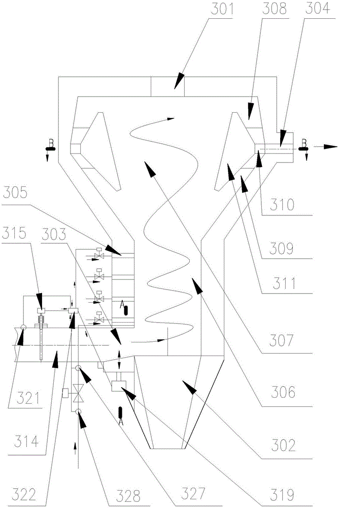
[0043] see Figure 1 to Figure 5 , is a preferred embodiment of the turbulent combustion device,

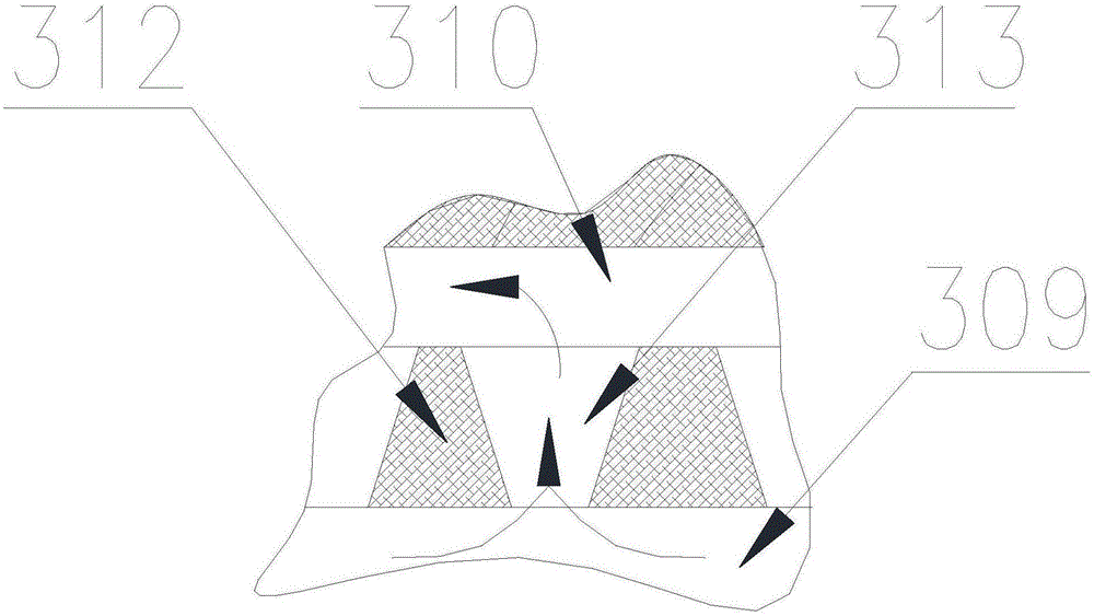
[0044] A turbulent combustion device, the top plate of the turbulent combustion device is provided with combustion chamber ignition and combustion-supporting holes 301, and the inner cavity of the turbulent combustion device includes a conical slag outlet 302, a combustion channel, etc. 306, V-cone channel 307, and the lower annular flue gas channel 309, annular exhaust flue 310, and upper annular flue gas channel 308 that surround the V-cone channel 307 from bottom to top. The bottom is small, the lower end of the side wall of the combustion channel 306 is provided with a tapered slag outlet 303 along the tangential direction, and a number of combustion-supporting air supply ports 305 are arranged on the side wall of the combustion channel 306, and each combustion-supporting air supply port 305 is located at Above the cone-shaped slag outlet 303, the lower annular flue gas pass...


PUM


Abstract

The invention discloses a mechanical fire grate type garbage gasification and incineration system and a turbulent combustion device. An inner cavity of the turbulent combustion device comprises a conical slag outlet, a combustion channel, a V-cone channel, a lower annular smoke channel, an annular exhausting flue and an upper annular smoke channel, wherein the conical slag outlet, the combustion channel and the V-cone channel are sequentially arranged from bottom to top, and the lower annular smoke channel, the annular exhausting flue and the upper annular smoke channel are sequentially arranged around the V-cone channel from bottom to top. A turbulent combustion device inlet is formed in the lower end of the side wall of the combustion channel in the tangential direction, the ventilation area of the lower annular smoke channel is gradually decreased from bottom to top, and the ventilation area of the upper annular smoke channel is gradually decreased from top to bottom. A tangential smoke outlet is formed in the side wall of the turbulent combustion device and communicates with the annular exhausting flue. The turbulent combustion device has high dust removal efficiency, combustion efficiency and heat recovery efficiency, and can achieve controllable combustion and controllable collection, reduce heat loss and effectively reduce pollutant emission.

Description

technical field [0001] The invention belongs to the technical field of solid waste incineration treatment, and in particular relates to a mechanical grate type garbage gasification incineration system and a turbulent combustion device. Background technique [0002] The existing waste treatment technologies mainly include incineration, sanitary landfill, composting, and waste recycling. Among the conventional waste treatment technologies, incineration has the advantages of obvious reduction effect, complete harmlessness, small land occupation, utilization of waste heat energy, and less secondary pollution, which meets the strategic requirements of my country's sustainable development. However, with the continuous improvement of environmental protection requirements at home and abroad, how to strengthen the control of secondary pollution is particularly important. Therefore, waste pyrolysis and gasification incineration technology is gradually pushed to the road of industrial...

Claims


Application Information

Patent Timeline
IPC IPC(8): F23G5/027F23J15/02F23L5/02F23L9/00F23G5/50F23G5/16F23G5/44
CPCF23G5/0276F23G5/16F23G5/444F23G5/50F23J15/027F23J2217/40F23L5/02F23L9/00
Inventor 林顺洪严欣平周雄李长江丁又青杨鲁徐明汤毅莫榴
Owner CHONGQING SANFENG ENVIRONMENTAL IND GRP
Why Eureka
Try Eureka