Device and process for treating chemical dangerous and waste sludge
A technology for sludge and hazardous waste, which is applied in the field of equipment for disposal of chemical hazardous waste sludge, can solve the problems of high requirements for equipment industrialization, large secondary pollution, and difficulty in practical application, and achieve the reduction of solvent residues, secondary Pollution is large and the effect of avoiding corrosion
- Summary
- Abstract
- Description
- Claims
- Application Information
AI Technical Summary
Problems solved by technology
Method used
Image
Examples
Embodiment 1
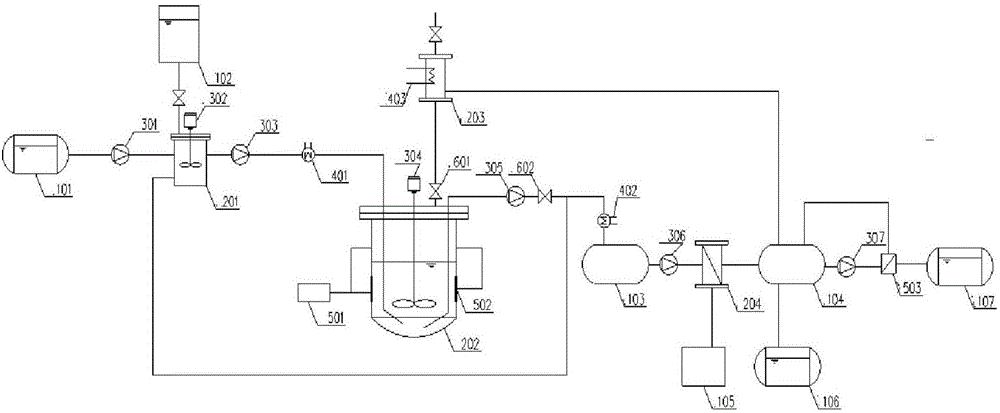
[0025] A device for treating chemical hazardous waste sludge, including storage tank A101, high-level storage tank 102, storage tank 103, mixed oil tank 104, storage tank B105, refined oil storage tank 106, sewage storage tank 107, and mixing tank 201 , reaction kettle 202, condensation tank 203, screw pump 301, agitator A302, high-pressure plunger pump 303, agitator B304, high-pressure pump 305, sludge pump 306, chemical pump 307, preheater 401, circulating water cooling device 402 , circulating water condensation device 403, ultrasonic generator 501, transducer 502, cross-flow ceramic membrane module 503 and pressure reducing valve 602; the storage tank A101 is connected to the screw pump 301 and the mixing tank 201 in turn; the high-level storage tank 102 is connected to the mixing tank 201; the mixing tank 201 is connected to the high-pressure plunger pump 303, the preheater 401 and the reactor 202 in turn, and the agitator A302 is arranged in it; the agitator B304 is place...
Embodiment 2
[0035] A device for treating chemical hazardous waste sludge, the device includes a storage tank A101, a high-level storage tank 102, a storage tank 103, a mixed oil tank 104, a storage tank B105, a refined oil storage tank 106, a sewage storage tank 107, Mixing tank 201, reaction kettle 202, condensation tank 203, screw pump 301, agitator A302, high-pressure plunger pump 303, agitator B304, high-pressure pump 305, sludge pump 306, chemical pump 307, preheater 401, circulating water Cooling device 402, circulating water condensing device 403, ultrasonic generator 501, transducer 502, cross-flow ceramic membrane module 503 and pressure reducing valve 602; the storage tank A101 is connected to the screw pump 301 and the mixing tank 201 in sequence; the The high-level storage tank 102 is connected to the mixing tank 201; the mixing tank 201 is connected to the high-pressure plunger pump 303, the preheater 401 and the reaction kettle 202 in turn, and the agitator A302 is arranged i...
Embodiment 3
[0046] A device for treating chemical hazardous waste sludge, the device includes a storage tank A101, a high-level storage tank 102, a storage tank 103, a mixed oil tank 104, a storage tank B105, a refined oil storage tank 106, a sewage storage tank 107, Mixing tank 201, reaction kettle 202, condensation tank 203, screw pump 301, agitator A302, high-pressure plunger pump 303, agitator B304, high-pressure pump 305, sludge pump 306, chemical pump 307, preheater 401, circulating water Cooling device 402, circulating water condensing device 403, ultrasonic generator 501, transducer 502, cross-flow ceramic membrane module 503 and pressure reducing valve 602; the storage tank A101 is connected to the screw pump 301 and the mixing tank 201 in sequence; the The high-level storage tank 102 is connected to the mixing tank 201; the mixing tank 201 is connected to the high-pressure plunger pump 303, the preheater 401 and the reaction kettle 202 in turn, and the agitator A302 is arranged i...
PUM
| Property | Measurement | Unit |
|---|---|---|
| Aperture | aaaaa | aaaaa |
| Aperture | aaaaa | aaaaa |
Abstract
Description
Claims
Application Information
 - R&D
- Intellectual Property
- Life Sciences
- Materials
- Tech Scout
- Unparalleled Data Quality
- Higher Quality Content
- 60% Fewer Hallucinations
Browse by: Latest US Patents, China's latest patents, Technical Efficacy Thesaurus, Application Domain, Technology Topic, Popular Technical Reports.
© 2025 PatSnap. All rights reserved.Legal|Privacy policy|Modern Slavery Act Transparency Statement|Sitemap|About US| Contact US: help@patsnap.com

