IGBT module structure reliability testing device having video monitoring function

A module structure and video monitoring technology, which is applied in the direction of measuring devices, single semiconductor device testing, semiconductor working life testing, etc., can solve problems such as key wire fusing, IGBT module failure, solder layer delamination, etc., to reduce false touches and misoperations The probability of increasing the load-bearing capacity and the effect of good fixation

Active Publication Date: 2017-01-11
HEBEI UNIV OF TECH
View PDF10 Cites 4 Cited by
  • Summary
  • Abstract
  • Description
  • Claims
  • Application Information

AI Technical Summary

Problems solved by technology

[0006] In addition, because the temperature of the IGBT module is constantly changing, the constantly fluctuating temperature will cause the thermal stress to repeatedly impact the solder layer, and the shear stress generated between the solder layers will cause fine cracks in the weak places of the solder layer. Under continuous impact, these tiny cracks will gradually expand, resulting in delamination and voids in the solder layer, which will lead to local overheating in the chip, which will lead to failure of the IGBT module
The chip and the chip, and the chip and the copper layer inside the IGBT module are generally connected by bonding wires. Since the bonding wire, the metal layer on the chip surface, and the copper layer are all made of different materials, the thermal expansion coefficients of various materials are different and fluctuate continuously. The temperature will cause the thermal stress to repeatedly impact the bond, which will easily cause the bond wire to peel off or warp off the pad. When some bond wires peel off or warp off the pad, all the current will concentrate on the remaining conductive bonds. On the wire, even the fuse of the key wire occurs, and then the IGBT module fails
[0007] At present, in the reliability test of the IGBT module, the change of the key wire, solder layer, and copper layer inside the IGBT module is usually observed manually with the naked eye. It is impossible to accurately observe and record the entire test process, and it is difficult to determine the failure location of the IGBT module.

Method used


Image

  • IGBT module structure reliability testing device having video monitoring function
  • IGBT module structure reliability testing device having video monitoring function
  • IGBT module structure reliability testing device having video monitoring function

Examples


Embodiment Construction

[0042] Embodiments of the present invention are described in further detail below in conjunction with the accompanying drawings:

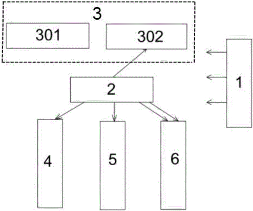
[0043] A kind of IGBT module structure reliability test device with video monitoring function, such as figure 1 As shown, it includes a power module 1 , an intelligent control module 2 , a sliding module 4 , a rotating module 5 , an acquisition module 6 and a telescopic module 3 . The power supply module 1 provides electric energy for other modules of the whole device. Described intelligent control module 2 comprises single-chip microcomputer module and computer, and the output end of single-chip microcomputer module in intelligent control module 2 connects the input end of sliding module 4, and sliding module 4 is output by the mode that slides on the sliding track by pulley; Described rotating module The input end of 5 is connected to the output end of the single-chip microcomputer module in the intelligent control module 2, and the output of th...


PUM


Abstract

The invention relates to an IGBT module structure reliability testing device having a video monitoring function. The IGBT module structure reliability testing device comprises a power supply module, a telescopic module, an intelligent control module, a sliding module, a rotating module, and an acquisition module. The power supply module is connected with other modules to provide electric energy. The intelligent control module is connected with the telescopic module, the sliding module, the rotating module, and the acquisition module to realize a test control function. The IGBT module structure reliability testing device is advantageous in that the design is reasonable; the constant changing of the internal chip, the solder layer, and the copper layer of the IGBT module during a testing process is acquired by adopting a visual sensor; the corresponding changing of the corresponding parts is determined, and the gradual changing of the internal structure of the IGBT is discovered, and after the IGBT loses efficacy, the part causing the failure of the IGBT is determined.

Description

technical field [0001] The invention belongs to the technical field of power electronic device detection, in particular to an IGBT module structure reliability test device with a video monitoring function. Background technique [0002] Insulated gate bipolar transistor (IGBT) is a composite fully-controlled voltage-driven power semiconductor device composed of BJT (bipolar transistor) and MOS (insulated gate field effect transistor). The IGBT device combines MOSFET and GTR. The advantages of this device are not only simple driving, high power level, low power consumption, but also low saturation voltage and good thermal stability. [0003] The IGBT module is a modular semiconductor product that is packaged by IGBT (insulated gate bipolar transistor chip) and FWD (freewheeling diode chip) through a specific circuit bridge. The IGBT module has the characteristics of energy saving, convenient installation and stable heat dissipation, and the IGBT module can be directly applied...

Claims


Application Information

Patent Timeline
Patent Type & Authority Applications(China)
IPC IPC(8): G01R31/26
CPCG01R31/2601G01R31/2642G01R31/2648
Inventor 李玲玲吕聪敏李志刚杨艳芳刘伯颖
Owner HEBEI UNIV OF TECH
Why Eureka
Try Eureka