Laser additive manufacturing equipment and method for metal parts

A technology of laser additive materials and metal parts, which is applied in the field of additive manufacturing, can solve the problems of affecting the use effect and the inability of the inner surface precision to meet the design requirements, and achieve the effect of flexible implementation

Active Publication Date: 2019-05-10
HUAZHONG UNIV OF SCI & TECH
View PDF12 Cites 1 Cited by
  • Summary
  • Abstract
  • Description
  • Claims
  • Application Information

AI Technical Summary

Problems solved by technology

In many cases, even if a lot of cost is spent on subsequent processing of such parts, the accuracy of the inner surface cannot meet the design requirements, affecting its use effect

Method used


Image

  • Laser additive manufacturing equipment and method for metal parts
  • Laser additive manufacturing equipment and method for metal parts
  • Laser additive manufacturing equipment and method for metal parts

Examples


Embodiment 1

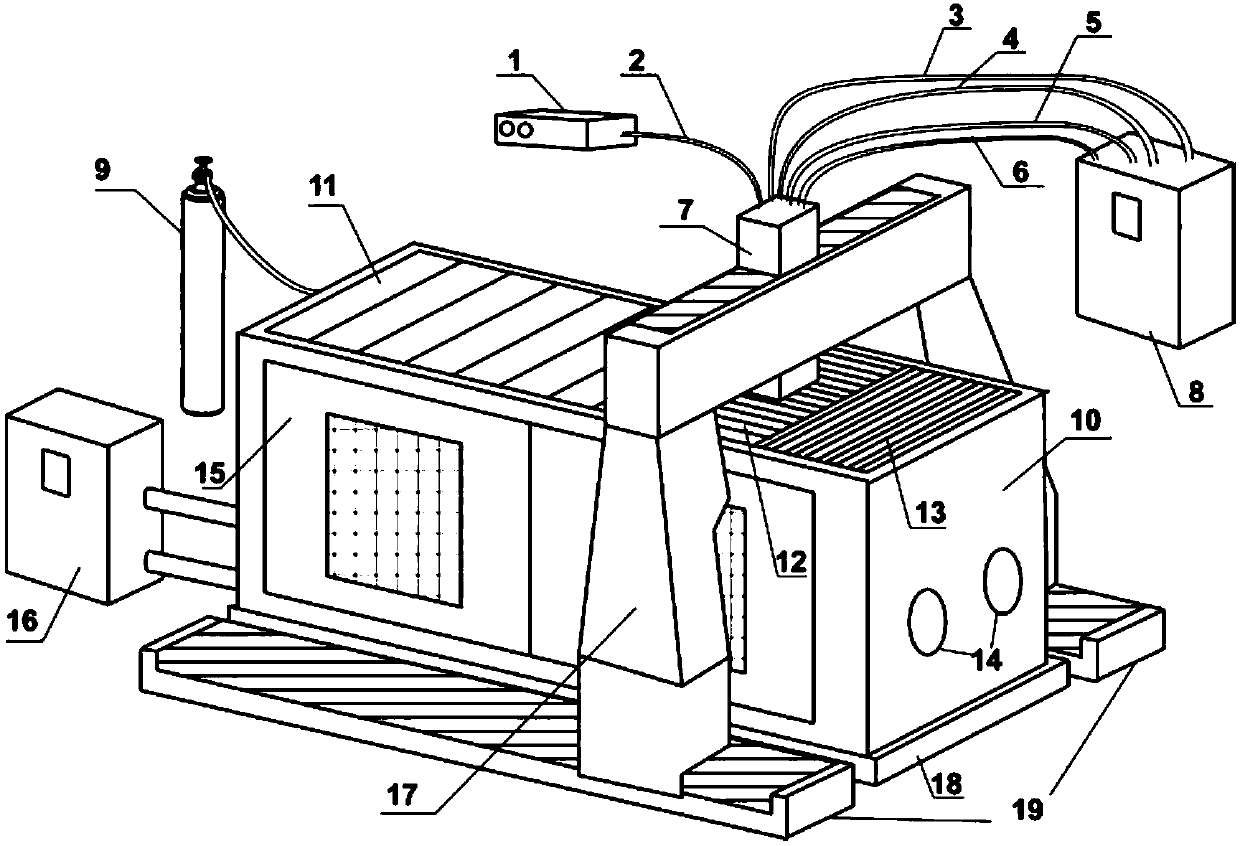
[0055] As shown in Figure 1, a laser additive manufacturing equipment provided by the example of the present invention includes a working cabin, a preset powder coating rapid prototyping component, a conformal cylinder setting and removal component, a machining component, a moving mechanism and a control system .

[0056] The working cabin includes a working cabin body 10, a protective gas source 9 and a dust removal system 16; the bottom of the working cabin body 10 is provided with a horizontal base 18, and the side is provided with a hatch 15 and a glove box joint 14; the protective gas source 9 and the dust removal system 16 is located outside the working cabin body 10; wherein, the protective gas source 9 is responsible for providing protective gas to the inside of the working cabin body 10; the inside of the dust removal system 16 is equipped with multi-stage filter elements and circulating fans, which are used to purify the inside of the working cabin body 10 due to high...

Embodiment 2

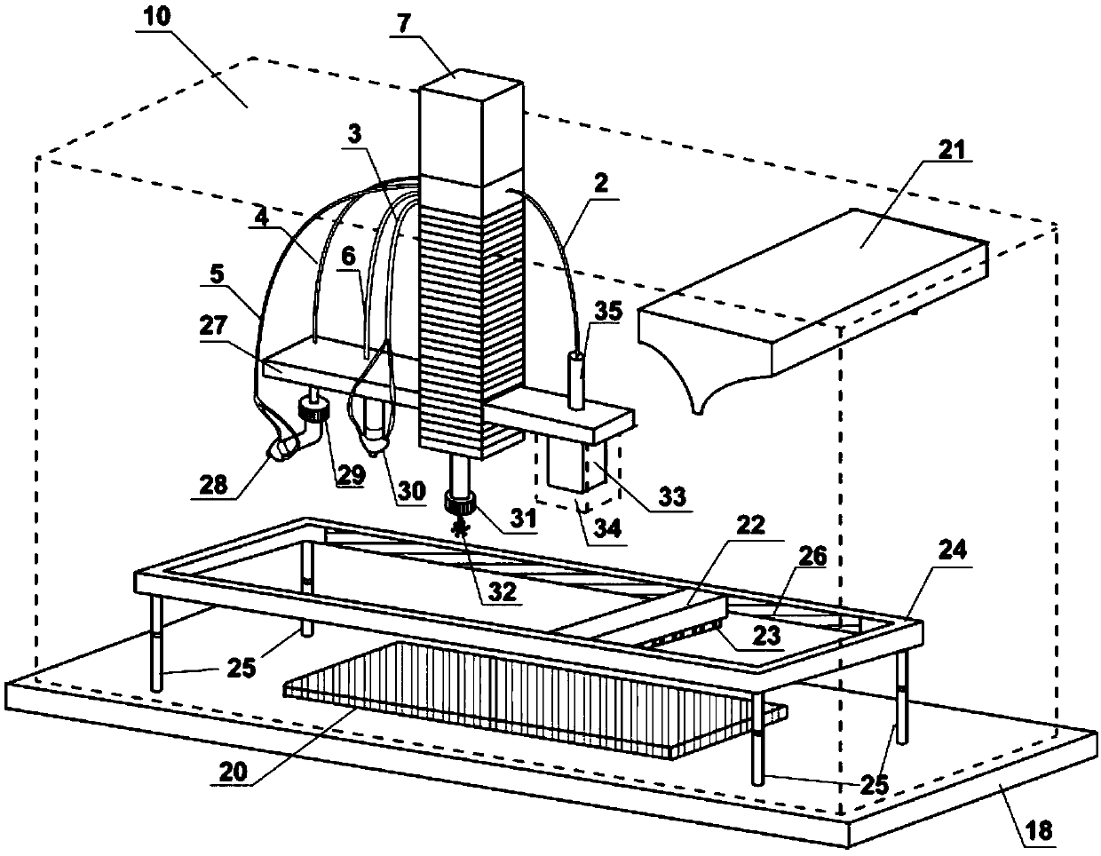
[0077] As shown in Figure 2, a laser additive manufacturing equipment provided by the example of the present invention includes a working cabin, a preset powder spreading rapid prototyping component, a conformal cylinder setting and removal component, a machining component, a moving mechanism and a control system .

[0078] The composition of the working cabin, the preset powder-spreading rapid prototyping component, the conformal cylinder setting and removal component, the mechanical processing component and the structure and function of the components contained in it are the same as those in Embodiment 1; wherein, the laser deposition and cutting host 8. The laser source 1, the protective gas source 9 and the dust removal system 16 are still located outside the working cabin body 10, the substrate 20, the powder storage chamber 21, the powder spreader 22, the scraper 23, the laser cutting head 28, the coaxial feeding nozzle 30, the mechanical The processing fixture 31 , cutt...

Embodiment 3

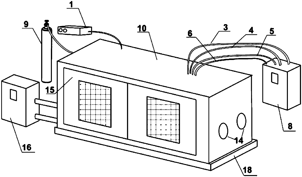
[0083] As shown in Figure 3, a laser additive manufacturing equipment provided by the example of the present invention includes a working cabin, a preset powder spreading rapid prototyping component, a conformal cylinder setting and removal component, a machining component, a moving mechanism and a control system .

[0084] The composition of the working cabin, the pre-set powder spreading rapid prototyping assembly, the mechanical processing assembly and the structure and function of the contained parts are the same as in Embodiment 1; wherein, the laser source 1, the protective gas source 9 and the dust removal system 16 are still in the working position. Outside the cabin 10, the substrate 20, the powder storage chamber 21, the powder spreader 22, the scraper 23, the machining fixture 31, the cutter 32, the scanning galvanometer 33, the dust cover 34, and the beam expander 35 are still located inside the working cabin 10 .

[0085] The follow-up cylinder setting and remova...


PUM


Abstract

The invention discloses a laser additive manufacturing equipment and method for metal parts. The equipment includes working cabin, pre-set powder spreading rapid prototyping components, conformal cylinder setting and removal components, machining components, moving mechanism and control system. First, use the conformal cylinder setting and removal component to set a conformal cylinder slice layer on the surface of the substrate that can surround the metal part slice contour, and the preset powder spreading rapid prototyping component lays a layer of metal powder inside it, and the powder Carry out laser selective melting to complete the forming of the first slice layer of metal parts; according to the precision requirements, mechanical processing components can be used to machine the formed slice layer of the part; Layer laser selective melting forming-machining (when necessary)" process, which can realize high-precision forming of metal parts of various sizes and structures at one time; shaped cylinder.

Description

technical field [0001] The invention belongs to the technical field of additive manufacturing, and in particular relates to a laser additive manufacturing equipment and method for metal parts. Background technique [0002] With the continuous improvement of the quality of high-energy beam equipment and the increasing development of three-dimensional data processing technology, the broad prospects and huge market of metal parts 3D printing technology have become an indisputable fact, and various high-energy beam additive manufacturing methods and equipment have also come into play. And born. [0003] At present, high energy beam additive manufacturing technology mainly uses laser beam, plasma beam, electron beam and electric arc as processing energy sources. Among them, laser additive manufacturing technology has become a common processing method for metal parts additive manufacturing technology due to its good formability and wide material adaptability. [0004] According ...

Claims


Application Information

Patent Timeline
Patent Type & Authority Patents(China)
IPC IPC(8): B22F3/105B33Y30/00B33Y10/00B33Y40/00
CPCB33Y10/00B33Y30/00B33Y40/00B22F10/00B22F10/60B22F12/53B22F10/28B22F12/49B22F10/50B22F10/32B22F10/40B22F10/25B22F12/60B22F10/80Y02P10/25
Inventor 曾晓雁魏恺文王泽敏李祥友朱海红熊伟蒋明
Owner HUAZHONG UNIV OF SCI & TECH
Why Eureka
Try Eureka