
Spatial light reception demodulation device

A demodulation device and spatial light technology, applied in the field of space optical communication, can solve problems such as the inability to meet the development needs of laser communication systems

Active Publication Date: 2017-02-01
XIAN INSTITUE OF SPACE RADIO TECH
View PDF5 Cites 18 Cited by
  • Summary
  • Abstract
  • Description
  • Claims
  • Application Information

AI Technical Summary

Problems solved by technology

However, the integration of communication and fine tracking based on space light, and the all-digital demodulation scheme to realize laser communication reception have not been mentioned in the open literature. This will not meet the development needs of future laser communication systems, and new research is required.

Method used


Image

  • Spatial light reception demodulation device
  • Spatial light reception demodulation device
  • Spatial light reception demodulation device

Examples


Embodiment Construction

[0045] Below in conjunction with accompanying drawing, the present invention will be described in further detail:

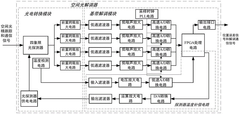
[0046] Such as figure 1 As shown, the spatial light receiving demodulation device of the present invention is composed of two parts: a photoelectric conversion module and a baseband demodulation module. in:

[0047] The photoelectric conversion module mainly includes four parts: a four-quadrant photodetector, a pre-transimpedance amplifier circuit, a photodetector power supply circuit and a temperature detection circuit.

[0048] The four-quadrant photodetector adopts S4402Si Quadrant APD produced by HAMAMATSU Company, which contains 4 avalanche photodiodes inside and has the optimal multiplication factor M=100, which can effectively improve the sensitivity of the receiving circuit.

[0049] The pre-transimpedance amplifier circuit is configured with the low-noise transimpedance amplifier OPA657 produced by TI. Because the signal current output by the four-qua...


PUM


Abstract

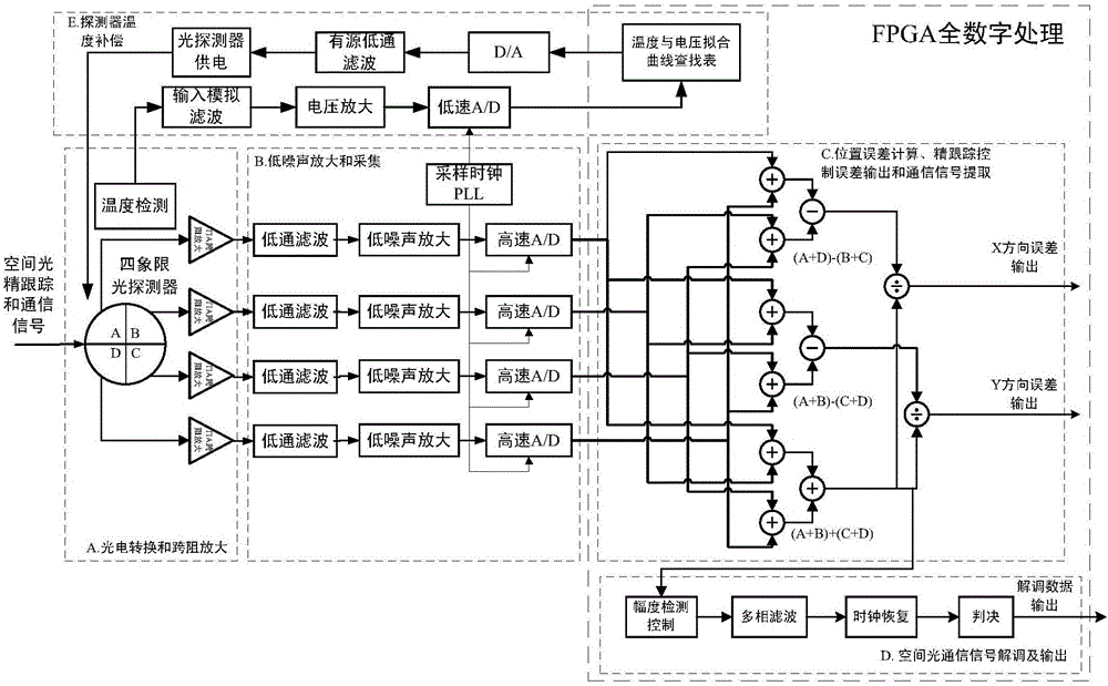
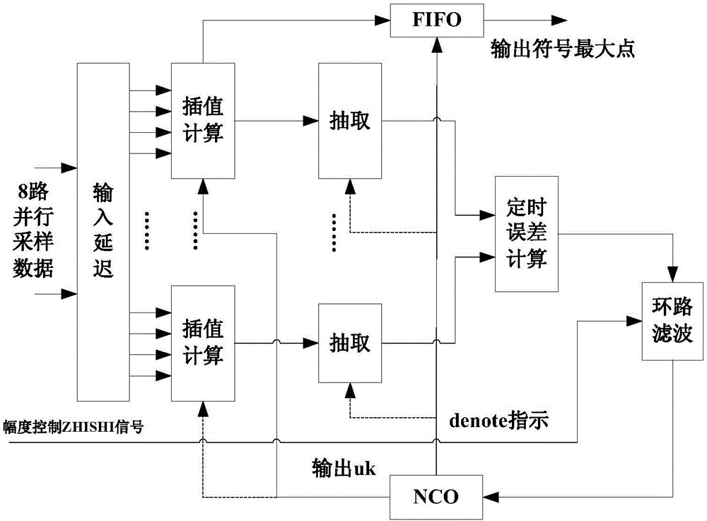
The invention provides a spatial light reception demodulation device comprising a four-quadrant photodetector, pre-transimpedance amplifier, a low pass filter, a low noise amplifier circuit, a sampling clock PLL circuit, a high-speed analog-to-digital conversion circuit, an FPGA processing circuit, an output interface circuit, and a photoelectric detector power supply and temperature compensation circuit. The spatial light reception demodulation device provided by the invention adopts the integrated design of precise tracking signals of spatial light positions and light communication signals, integrates spatial light position error tracking calculation with light reception demodulation, thereby simplifying an optical front end of spatial light communication; by means of the amplification of a low noise amplifier and FPGA amplitude detection and control, high sensitivity, wide dynamic range reception and amplification, and precise tracking position error information extraction of spatial light are realized; and meanwhile, by means of the software radio idea, high speed A / D collection and FPGA full digital processing are adopted to realize reception and collection, demodulation and recovery and position error control of the spatial light, and the temperature compensation of the detector.

Description

technical field [0001] The invention belongs to the field of space optical communication, and relates to a space light receiving all-digital demodulation device. Background technique [0002] As my country's demand for high-speed and large-capacity space information acquisition, processing and transmission is getting higher and higher, space optical communication has become the main means and technical realization of high-bandwidth satellite communication in the future. Satellite laser communication terminals that achieve high bit rate, light weight, miniaturization and low power consumption have an important strategic position in the development of my country's space technology and applications, and have important application prospects. [0003] The current laser communication system mainly focuses on the discussion of the system implementation scheme or the research on the principle of optical fiber communication, while the space light receiving demodulation is only discus...

Claims


Application Information

Patent Timeline
Patent Type & Authority Applications(China)
IPC IPC(8): H04B10/11H04B10/61
CPCH04B10/11H04B10/612H04B10/65
Inventor 左金钟汪滴珠杨光文杨新权郭精忠徐常志杨丽
Owner XIAN INSTITUE OF SPACE RADIO TECH
Learn More