
Electrical small loop antenna system in micro wireless sensor

A wireless sensor and loop antenna technology, which is applied in the field of small wireless sensor internal electric small loop antenna, can solve the problems of inoperable sensors, complex structure, low antenna gain, etc.

Inactive Publication Date: 2017-02-08
杨明
View PDF4 Cites 2 Cited by
  • Summary
  • Abstract
  • Description
  • Claims
  • Application Information

AI Technical Summary

Problems solved by technology

[0005] For ceramic substrate antennas, R.W. Ziolkowski and A. D.Kipple published an article titled "Antenna design of 60-Ghz micro-radarsystem in-package for noncontact vital sign detection" in IEEE Antennas and Wireless Propagation Letters in 2012, in which they proposed Ceramic substrate antennas are generally suitable for high frequencies, and it is difficult to design in low frequencies
[0006] For the miniaturization of 434 MHz antenna, Wendong Liu published an article titled "A novel miniaturized antenna for ISM 433MHz wireless system" in the Electrical Design of Advanced Packaging and Systems Symposium in 2013, in which he proposed to use a large-area vertical ground plane The 434 MHz antenna, with a size of 75×51 mm, is too large to work in the sensor package
In 2013, Albert Sabban published an article entitled "Compact Tunable Printed Antennas for Medical and Commercial Applications" at the IEEE International Conference on Microwaves, Communications, Antennas and Electronics Systems, in which he proposed a slotted dipole-loaded antenna, an antenna The gain can reach up to 2 dBi, and the minimum size of the antenna can reach 5×5×0.05 cm through size optimization, which can be used outside the sensor package, but still cannot be loaded into the sensor package for use
[0007] In 2014, Ni Yang, Ye Ming, and Wang Xiaojing published an article titled "Small Dual-band Microstrip Antenna Applied to ISM Band" in Electronic Measurement Technology. In this article, a dual-band ISM antenna was studied, although the antenna can cover ISM 433.05~ 434.79MHz, two frequency bands of 2.4~2.5 GHz, but the antenna gain is low at 434 MHz, and the structure is complex. At the same time, the efficiency test is not given in the article, which limits the actual engineering use of the antenna

Method used


Image

  • Electrical small loop antenna system in micro wireless sensor
  • Electrical small loop antenna system in micro wireless sensor
  • Electrical small loop antenna system in micro wireless sensor

Examples


Embodiment 1

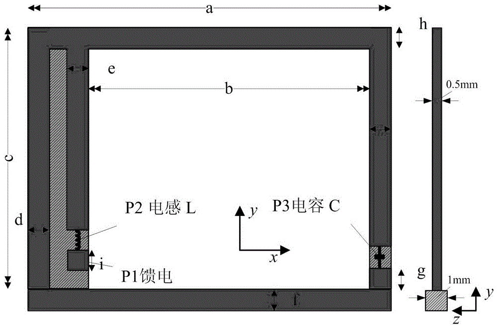
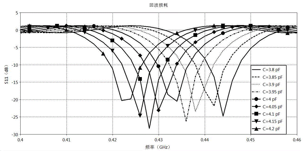
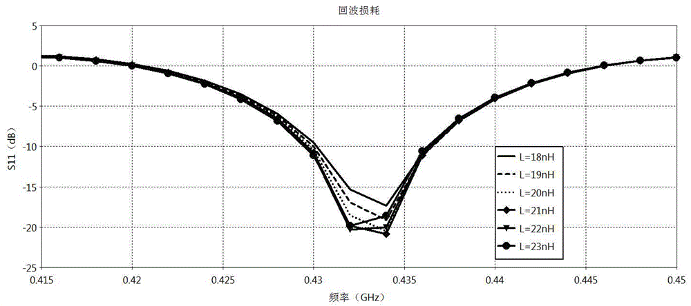
[0032] The structure of the antenna is as figure 1 shown. Through the lumped loading technology, a lumped capacitor is loaded on the ground terminal to adjust the antenna resonant frequency, and a lumped inductance is loaded on the feed port to adjust the impedance matching. Both the capacitor and the inductor are packaged in 0603, and finally the antenna radiation unit structure is Optimization, the same "grounding" treatment is carried out at the other end of the antenna, so as to effectively increase the current path and achieve the purpose of miniaturization.

[0033] Table 1 Dimensions of each part of the antenna: (mm)

[0034] a b c 18 14 12 C L d=e=f=g=h=i 4pF 21nH 1

[0035] The dimensions of each part of the antenna are shown in Table 1. The upper part of the antenna is the main radiation branch, and the single-sided FR4 dielectric substrate is selected, and its relative permittivity is loss tangent , with a thickness of 0.5 ...


PUM


Abstract

The invention relates to an electrical small loop antenna system in a micro wireless sensor. The electrical small loop antenna system in the micro wireless sensor comprises a substrate, a feed terminal and a ground terminal, wherein the substrate is an FR4 medium substrate; the feed terminal is loaded with lumped inductance; the ground terminal is loaded with lumped capacitance; the capacitance and the inductance adopt a 0603 encapsulation mode; the FR4 medium substrate has a relative dielectric constant Epsilon of 4.4, a loss tangent value tanDelta of 0.02, and the thickness of 0.5mm; the electrical small loop antenna works at a frequency band ranging from ISM433.05 to 434.79MHz. Through a lumped loading technology, the size is optimized, the antenna with smaller volume can be three-dimensionally encapsulated with a radio-frequency circuit. The impedance matching is adjusted through the lumped loading capacitance and inductance, so that -10dB bandwidth of the antenna is larger than 7MHz, and the radiation gain is larger than 0.5dBi. The return loss is about 4MHz, the radiation efficiency is larger than 20 percent, and the directionality is better. Compared with a traditional 433MHz antenna with an ISM frequency band, the electrical small loop antenna has the characteristics of smaller size, simple structure, easiness in tuning and the like.

Description

technical field [0001] The invention relates to the technical field of electric small loop antennas, and more specifically relates to an electric small loop antenna inside a miniature wireless sensor. Background technique [0002] In recent years, with the concept of "Internet +", a large number of micro sensors, wearable devices and intelligent hardware have emerged. Compared with the application of traditional antennas, miniature sensors have higher requirements for antenna miniaturization. On the one hand, due to the small size of the sensor and the limited built-in battery capacity, using the lower ISM frequency band of 300 MHz to 3 GHz can reduce the communication propagation loss. However, the wavelength of this frequency band is 0.1 to 1 meter, which is generally 50 to 100 times the size of the sensor; on the other hand, due to the reduction of the net space of the antenna, the antenna built in the sensor package belongs to the category of electric small antenna, Haro...

Claims


Application Information

Patent Timeline
Patent Type & Authority Applications(China)
IPC IPC(8): H01Q1/38H01Q1/50H01Q1/52
CPCH01Q1/38H01Q1/50H01Q1/52
Inventor 杨明周金芝
Owner 杨明
Learn More