Oily sludgestepwisecontinuous pyrolysis and energy supplying integration method and device

The technology of an oil-water separation device and a cracking device is applied in the field of step-by-step continuous pyrolysis and energy supply integration of oily sludge, which can solve the problems of no good utilization of residual oil and low energy utilization rate of the solution, so as to solve the problem of energy recycling. The effect of utilization problems, improving energy utilization, and reducing pyrolysis costs

Inactive Publication Date: 2017-02-22
中海油能源发展股份有限公司北京安全环保工程技术研究院 +2
View PDF2 Cites 8 Cited by
  • Summary
  • Abstract
  • Description
  • Claims
  • Application Information

AI Technical Summary

Problems solved by technology

However, at present, there is no good solution for the utilization of residual oil recovered after pyrolysis, and there are a series of technical problems such as low overall energy utilization rate in the pyrolysis process.

Method used


Image

  • Oily sludgestepwisecontinuous pyrolysis and energy supplying integration method and device

Examples


Embodiment 1

[0039] An integrated method for step-by-step continuous pyrolysis and energy supply of oily sludge, comprising the following process:

[0040] Step 1: Primary cracking

[0041] The oily sludge enters the first-stage cracking device from the oily sludge feed port, and is indirectly heated by gas, and the material is transported to the discharge end of the first-stage cracking device through the built-in screw conveyor, and the pyrolysis oil gas produced is produced by the first-stage pyrolysis device. The pyrolysis gas outlet of the cracking unit is connected to the pyrolysis gas inlet of the secondary cracking unit;

[0042] Step 2: Secondary cracking

[0043] The pyrolysis oil and gas produced by primary cracking enters the secondary cracking device for cracking; the pyrolysis oil and gas entering the secondary cracking device mainly contains: tar, water vapor, hydrogen, carbon monoxide, small molecular alkanes, olefins and large molecular oil and gas, etc. Hydrogen compoun...

Embodiment 2

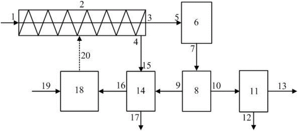
[0049] An integrated step-by-step continuous pyrolysis and energy supply device for oily sludge, including a primary cracking device 2, a secondary cracking device 6, a spray tower 8, an oil-water separation device 11, a gas drying device 14, and a combustion device 18; The first-stage cracking device 2 has a built-in oily sludge screw conveying structure. The pyrolysis gas outlet 3 of the first-stage cracking device is connected to the pyrolysis gas inlet 5 of the second-stage cracking device. The slag outlet 4 of the first-stage cracking device is connected to the slag inlet 15 of the gas drying device. The cracking gas outlet 7 of the stage cracking device is connected to the spray tower 8, the liquid phase outlet 10 of the spray tower is connected to the oil-water separation device 11, the gas phase outlet 9 of the spray tower is connected to the gas drying device 14, and the non-condensable gas outlet 16 of the gas drying device is connected to the The combustion device 18...


PUM


Abstract

The invention relates to an oily sludgestepwisecontinuous pyrolysis and energy supplying integration method and device, and belongs to the technical field of organic matter pyrolysis. The oily sludgestepwisecontinuous pyrolysis and energy supplying integration method includes the steps of 1 primary pyrolysis, wherein oily sludge enters a primary pyrolysis device to carry out pyrolysis; 2 secondary pyrolysis, wherein pyrolysis oil gas enters a secondary pyrolysis device to carry out pyrolysis; 3 spray and gas-liquid separating, wherein gas and liquid phases are separated through spraying; 4 gas drying and combusting. The gas phase enters a gas drying device, and the dried gas can serve as a clean energy source to heat the primary pyrolysis device. The oily sludgestepwisecontinuous pyrolysis and energy supplying integration device comprises the primary pyrolysis device, the secondary pyrolysis device, a spray tower, an oil-water separating device, the gas drying device and a combustion device, and the combustion device and the primary pyrolysis device are arranged oppositely. The oily sludgestepwisecontinuous pyrolysis and energy supplying integrationdevice has the advantages that multi-level pyrolysis is adopted, energy can be controlled by the pyrolysis devices themselves, and energy can be used efficiently.

Description

technical field [0001] The invention belongs to the technical field of pyrolysis of organic matter, in particular to a step-by-step continuous pyrolysis and energy supply integrated method and device for oily sludge. In particular, it relates to a method and device for energy supply integrated conversion of oily sludge through pyrolysis, catalysis, gas phase drying and reuse, which can realize the self-sustained heating conversion of oily sludge pyrolysis to the greatest extent. Background technique [0002] At present, there are mainly two mature oily sludge treatment methods: one is to use incineration technology; the other is to use mechanical separation. But at present, these two methods have disadvantages in the process of treating oily sludge. Incineration process, with the improvement of environmental protection laws and regulations, the requirements for tail gas treatment are becoming more and more stringent, and the treatment cost is gradually increasing; mechanica...

Claims


Application Information

Patent Timeline
Patent Type & Authority Applications(China)
IPC IPC(8): C02F11/10C02F101/32
CPCY02W10/40C02F11/10C02F2101/32
Inventor 马蒸钊谢江浩刘涛王新新白鹤曹兴涛
Owner 中海油能源发展股份有限公司北京安全环保工程技术研究院
Why Eureka
Try Eureka