Terahertz photoconductive phased-array antenna system

A phased array antenna and photoconductive technology, applied in the field of terahertz radiation, to achieve the effects of increasing radiation power, improving the controllability of the pattern, and increasing the gain

Active Publication Date: 2017-02-22
FUJIAN INST OF RES ON THE STRUCTURE OF MATTER CHINESE ACAD OF SCI
View PDF6 Cites 15 Cited by
  • Summary
  • Abstract
  • Description
  • Claims
  • Application Information

AI Technical Summary

Problems solved by technology

Antenna arrays based on electronics can be made into phased array antennas (Phase array antenna) by means of electrical phase shifting, but the upper frequency limit is still in the low frequency band of terahertz

Method used


Image

  • Terahertz photoconductive phased-array antenna system
  • Terahertz photoconductive phased-array antenna system
  • Terahertz photoconductive phased-array antenna system

Examples


Embodiment 1

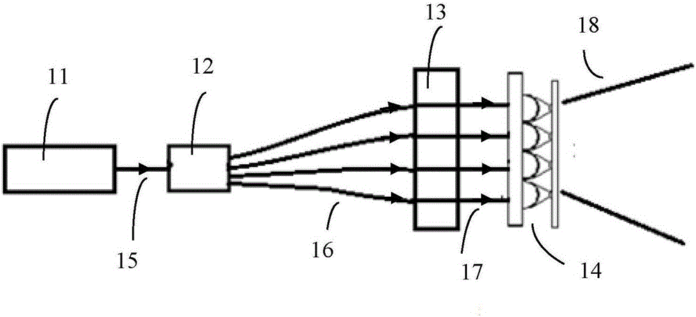
[0041] In this embodiment, the light delay controller 13 adopts a glass sheet delay mode. The function of the glass lamella is to control the amount of time that the pump light incident on the antenna element is delayed.

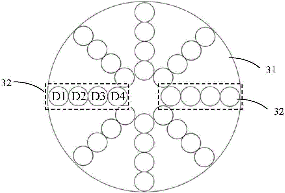
[0042] Described light delay controller 13 comprises disc 31 and a plurality of working areas 32 ( image 3 Shown by the dotted line in the center), a plurality of working areas 32 are arranged at equal intervals along the circumferential direction in the disc 31, and each working area 32 includes N glass flakes, and the N glass flakes are arranged radially along the disc 31, and each working The N glass flakes included in the area 32 have the same shape as the microlens array of the terahertz photoconductive array antenna 14 on the plane perpendicular to the optical path. Only one working area 32 enters the path of the pump light at a time through the mechanical rotation.

[0043] image 3 It shows that eight working areas 32 are arranged in the disc 31 at...

Embodiment 2

[0053] In this embodiment, the optical delay controller adopts an optical switch delay mode.

[0054] Figure 5 A structural diagram of the optical switch delay is given by the optical delay controller 13. The optical switch 51 adopts a micromirror reflective MEMS optical switch array formed by micro-nano processing, and an optical switch controller 52 is used to control the micromirror reflective MEMS optical switch. Various delays of the pumping light on the antenna array 142 can be obtained by the closed combination of the arrays. Each optical fiber coming out of the fiber coupler 12 is connected to one row of optical switches 51 , passes through n=3 optical switches 51 , and finally exits to the microlens on the terahertz photoconductive array antenna 14 . Each optical switch 51 can select light to pass through one of the two routes with different lengths, and three optical switches can be obtained through different combinations of three optical switches. 2 Different del...

Embodiment 3

[0056] In this embodiment, the optical delay controller adopts an electro-optic modulation delay mode.

[0057] In this way, the pump light is time-delayed using an optical waveguide 61 made of electro-optic crystals. Different voltages are applied to the electro-optic crystal to change the refractive index and control the delay of the pump light.

[0058] The laser source 11 is divided into two beams of polarized light by the polarization beam splitter 62, wherein one beam 63 can be expanded to be used as the detection light of the terahertz frequency domain spectrometer, and the other beam is divided into N beams of pump light equally by the fiber coupler 12, and then N beams of pumping light are respectively coupled into the optical waveguide 61 made of N z-cut KDP electro-optic crystals (the polarization direction of the light and the electro-optic crystal x 1 The intrinsic polarization directions of the terahertz photoconductive array antenna 14 are coupled to the microl...


PUM


Abstract

The invention relates to a terahertz photoconductive phased-array antenna system. The system comprises a laser source, an optical fiber coupler, a light delay controller and a terahertz photoconductive array antenna, wherein the optical fiber coupler is used for coupling the pump light generated by the laser source into an optical fiber; the light delay controller is used for controlling the delaying time of the pump light outputted by the optical fiber coupler and generating N beams of pump light at different delaying time; N is a natural number more than 1; the terahertz photoconductive array antenna is used for receiving the N beams of pump light at different delaying time outputted by the light delay controller; each beam of pump light is focused and irradiated on a corresponding bias antenna unit and then the terahertz irradiation is stimulated and generated. According to the terahertz photoconductive phased-array antenna system, the light delay controller is introduced into a pump light path of the photoconductive antenna array and the radiation phase is controlled so as to increase the radiation power of the array antenna and change the direction angle of the wave beam.

Description

technical field [0001] The invention belongs to the technical field of terahertz radiation, and in particular relates to a terahertz photoconductive phased array antenna system. Background technique [0002] Terahertz (THz / terahertz) radiation (0.1THz-10THz) technology is the frontier field in the field of electromagnetic waves, between the field of photonics and electronics: using the method of electronics, 0.3THz is basically the upper limit of its frequency; using photons The effect of the method of learning is not satisfactory. Terahertz radiation technology is called "terahertz gap" because of its immaturity. Compared with other electromagnetic wave bands, terahertz has unique properties and has great application prospects in medical, security inspection, materials and other fields. [0003] High-power terahertz source is an important bottleneck of terahertz technology, and terahertz antenna, as a kind of terahertz radiation source, is a research hotspot. One way to ...

Claims


Application Information

Patent Timeline
Patent Type & Authority Applications(China)
IPC IPC(8): H01Q1/50H01Q15/02H01Q21/00H01Q23/00
CPCH01Q1/50H01Q15/02H01Q21/00H01Q23/00
Inventor 陈景源林中晞徐玉兰林琦苏辉
Owner FUJIAN INST OF RES ON THE STRUCTURE OF MATTER CHINESE ACAD OF SCI
Why Eureka
Try Eureka