Multilayer film

A laminated film and laminated technology, applied to layered products, synthetic resin layered products, instruments, etc., can solve problems such as insufficient hydrolysis resistance, and achieve excellent outdoor durability

Active Publication Date: 2017-02-22
TORAY IND INC
View PDF10 Cites 4 Cited by
  • Summary
  • Abstract
  • Description
  • Claims
  • Application Information

AI Technical Summary

Problems solved by technology

The outdoor durability of 10 years or more is required, so high hydrolysis resistance is required, but the hydrolysis resistance of the conventional heat ray reflective film is insufficient

Method used


Image

  • Multilayer film
  • Multilayer film
  • Multilayer film

Examples


Embodiment 1

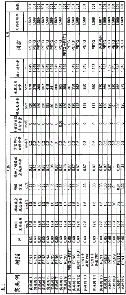
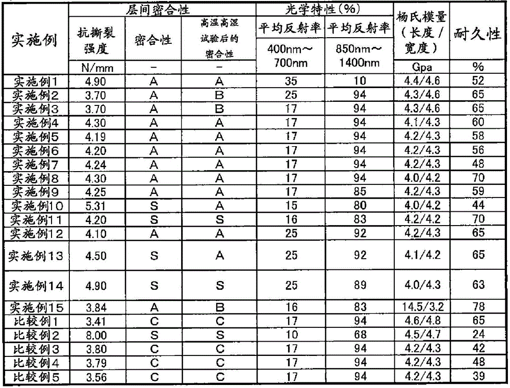
[0134] As the polyester A, PEN1 was used, and for the polyester B, PET obtained by copolymerizing 33 mol% of cyclohexanedimethanol (hereinafter referred to as PETG. Part number: GN001, manufactured by Istman Chemical Co., Ltd.) was used. As a result of measuring the heat of fusion of polyester by DSC, PEN1 was a crystalline polyester, and PETG was an amorphous polyester. Polyester A and polyester B were melted at 290°C by extruder respectively, passed through 5 pieces of FSS-type leaf disk filters, then passed through gear pumps and filters, and then made use of a 201-layer feed die set to make them confluence. The thickness of each layer of the merged polyester A and B in the feed die set is substantially constant from the surface side to the opposite surface side, forming a structure consisting of 101 layers of polyester A and 100 layers of polyester B. Alternately laminated structure along the thickness direction. The adjustment of the thickness of each layer was adjusted...

Embodiment 2

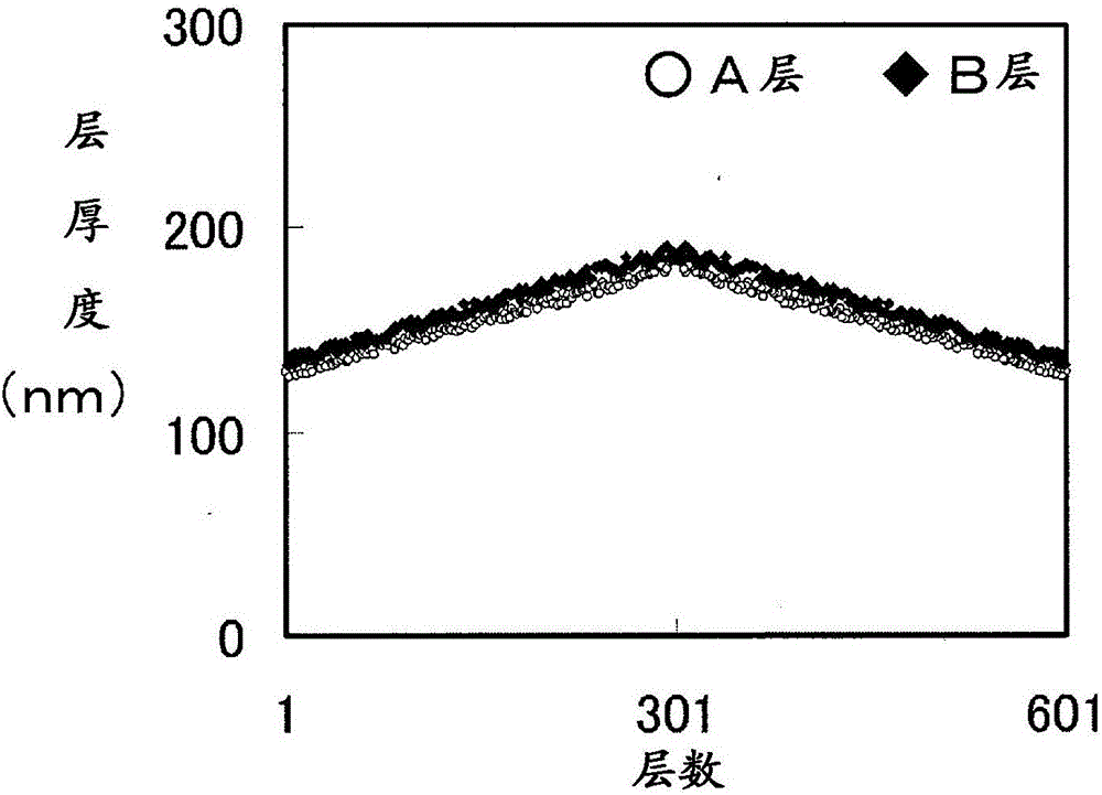
[0139]While measuring with a gear pump so that the ratio of optical thickness except for the thick film layer of the film is polyester A / polyester B = 1, a configuration using two slit plates with 301 slits The 601-layer lamination device is combined to form a laminated body in which 601 layers are alternately laminated along the thickness direction. The method of producing a laminate is carried out in accordance with the description in paragraphs [0053] to [0056] of JP-A-2007-307893. In addition, since there are layers formed by overlapping layers A, the number of gaps in the slit plate is 602. In addition, in order to make the reflection band with a wavelength of 1200nm or less be a polymer multilayer laminate, and the average reflectance of a wavelength of 850nm or more and 1200nm or less is 60% or more, the slit design is based on the layer thickness of the laminated film obtained through the following steps distributed as figure 1 Designed as shown. Then, it carried ou...

Embodiment 3

[0141] Except having changed sodium dihydrogen phosphate into potassium dihydrogen phosphate, it carried out similarly to the manufacturing method of PEN1, and produced PEN2, and carried out similarly to Example 2, and obtained the biaxially stretched film. As shown in Table 1, the resulting film exhibited substantially equivalent properties to Example 2.


PUM

PropertyMeasurementUnit
glass transition temperatureaaaaaaaaaa
thicknessaaaaaaaaaa
thicknessaaaaaaaaaa

Abstract

The present invention provides a multilayer film which reflects light within a specific band, and which is free from the problem of delamination that occurs in cases where a polyethylene naphthalate resin is used therefor. A multilayer film which has 201 or more layers obtained by alternately laminating layers A that are formed of a polyester A containing ethylene-2,6-naphthalate as a main repeating unit and layers B that are formed of a polyester B containing ethylene terephthalate as a main repeating unit and having a refractive index lower than that of the polyester constituting the layers A. This multilayer film is characterized in that the polyester A satisfies the following requirements. (1) The amount of terminal carboxylic acid groups is from 5 eq/t to 20 eq/t (inclusive). (2) An alkali metal phosphate salt is contained in an amount of from 1.3 mol/ton to 3.0 mol/ton (inclusive), and phosphoric acid is contained at a molar ratio of from 0.4 times to 1.5 times (inclusive) relative to the alkali metal phosphate salt. (3) The intrinsic viscosity is from 0.55 to 0.63 (inclusive).

Description

technical field [0001] The present invention relates to a multilayer laminated film that selectively reflects light in a specific wavelength band by the difference in refractive index between layers and the thickness of each layer. Background technique [0002] Multilayer laminated film utilizing light interference Multilayer laminated film with metallic luster (Patent Document 1, Patent Document 2), Multilayer laminated film with near-infrared reflection function (Patent Document 3), and polarized light reflection characteristic are known. Polarizing reflective film, dichroic filter, monochromatic filter, etc. These have an interference reflection function by laminating two types of resins with different refractive indices alternately, but in order to increase the reflectance, it is necessary to select resins with greatly different refractive indices. For example, in Patent Document 4, polyethylene 2,6-naphthalate (hereinafter referred to as PEN) is used for a layer having...

Claims


Application Information

Patent Timeline
Patent Type & Authority Applications(China)
IPC IPC(8): B32B27/36C08G63/189G02B5/26
CPCB32B27/36C08G63/189G02B5/26
Inventor 园田和卫增田嘉丈合田亘坂本纯宇都孝行
Owner TORAY IND INC
Why Eureka
Try Eureka