QKD system and method based on COW protocol
A protocol and quantum technology, applied in transmission systems, digital transmission systems, and key distribution, can solve the problems of narrow-linewidth CW lasers, which are expensive, difficult to popularize and apply on a large scale, difficult to integrate, and miniaturized, to achieve product integration , Eliminate the base matching problem and reduce the preparation cost
- Summary
- Abstract
- Description
- Claims
- Application Information
AI Technical Summary
Problems solved by technology
Method used
Image

Examples
Embodiment 1
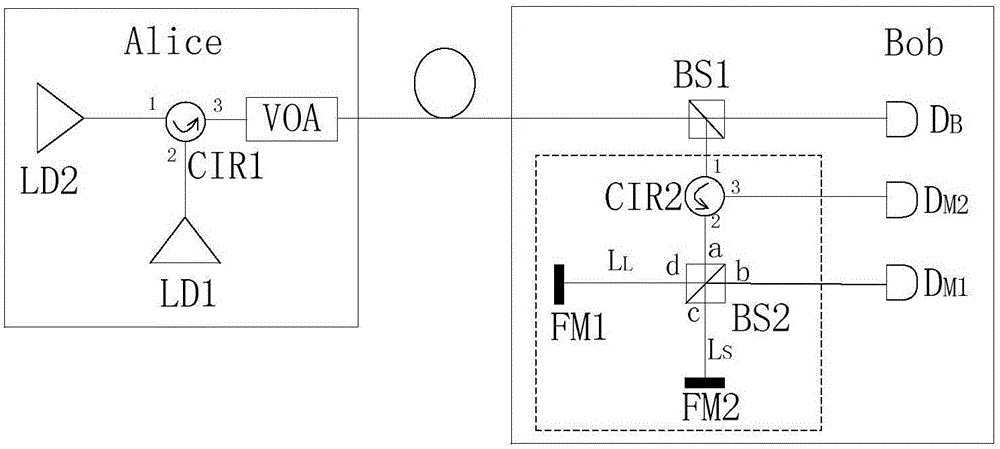
[0048] The QKD system based on the COW protocol of the present embodiment is such as figure 1 As shown, it includes the quantum key encoding end Alice, the quantum key decoding end Bob, and the quantum key distribution channel connecting Alice and Bob.
[0049] Alice is provided with a phase-modulated light source for outputting the double-pulse sequence signal light and an optical attenuator VOA (in this embodiment, an adjustable optical attenuator for attenuating the double-pulse sequence signal light) attenuated to the single-photon level).
[0050] Such as figure 1 As shown, the phase modulation light source of this embodiment includes a pulse generation laser LD1, a phase preparation laser LD2, and a first three-port circulator CIR1; the three ports of the first three-port circulator CIR1 are respectively the first port 1 along the optical path. , the second port 2 and the third port 3. Wherein, the first port 1 and the second port 2 are connected to the pulse generati...
Embodiment 2
[0093] The QKD system and method in this embodiment are the same as those in Embodiment 1, the difference is that, compared with the QKD system in Embodiment 1, the QKD system in this embodiment performs Improve. Specific as Figure 4 As shown, the third beam splitter BS3 as the third beam splitting module is additionally provided, the first optical fiber delay line DL1 cancels the third single photon detector D M2 . Port b of the second beam splitter BS2 is connected to an input port of the third beam splitter, port 3 of the second three-port circulator is connected to another input port of the third beam splitter through an optical fiber delay line DL, and the third The output port of the beam splitter is connected to the second single photon detector D M1 connected.
[0094] The delay time of the first optical fiber delay line DL1 in this embodiment can be set as required.
[0095] By setting the first fiber delay line DL1, the second single photon detector D M1 Two d...
Embodiment 3
[0098] The same as Embodiment 2, the difference is that the coherence detection unit at the Bob end does not set a detection subunit separately, such as Figure 5 As shown, the second single photon detector D is removed M1 , additionally set a fourth beam splitter BS4 and a second fiber delay line DL2 as the fourth beam splitting module. An output port of the first beam splitter BS1 is connected with an input port of the fourth beam splitter, port b of the second beam splitter BS2 is connected with an input port of the third beam splitter, and the port of the second three-port circulator 3 is connected to the other input port of the third beam splitter through the first fiber delay line DL1, and the output port of the third beam splitter is connected to the fourth beam splitter BS4 through the second fiber delay line DL2.
[0099] In this embodiment, the delay durations of the first fiber delay line DL1 and the second fiber delay line DL2 can be set as required.
[0100] By ...
PUM
 Abstract
Description
Claims
Application Information
 - R&D
- Intellectual Property
- Life Sciences
- Materials
- Tech Scout
- Unparalleled Data Quality
- Higher Quality Content
- 60% Fewer Hallucinations
Browse by: Latest US Patents, China's latest patents, Technical Efficacy Thesaurus, Application Domain, Technology Topic, Popular Technical Reports.
© 2025 PatSnap. All rights reserved.Legal|Privacy policy|Modern Slavery Act Transparency Statement|Sitemap|About US| Contact US: help@patsnap.com