Diesel engine high-pressure common rail system

A high-pressure common rail system and high-pressure common rail technology are applied in the direction of charging system, mechanical equipment, engine components, etc., which can solve the problems of poor working performance of diesel engines, difficult to withstand oil pressure, and excessive structural size, etc., and reach the damping limit The effect of maximum fuel pressure, damping fuel pressure fluctuations, good pressure accumulation and distribution of fuel

Active Publication Date: 2017-03-22
常州威曼新能源有限公司
View PDF8 Cites 5 Cited by
  • Summary
  • Abstract
  • Description
  • Claims
  • Application Information

AI Technical Summary

Problems solved by technology

Since diesel engines in the prior art are usually equipped with multiple cylinders, the length of the high-pressure common rail pipe usually needs to be very long. Image, further, the domestic high-pressure common rail pipe in the prior art is too long due to the structural size, limited by the machining accuracy, it is difficult to withstand high enough oil pressure, and it is easy to produce pressure fluctuations during use, which in turn affects the working performance of the di

Method used


Image

  • Diesel engine high-pressure common rail system
  • Diesel engine high-pressure common rail system
  • Diesel engine high-pressure common rail system

Examples


Embodiment 1

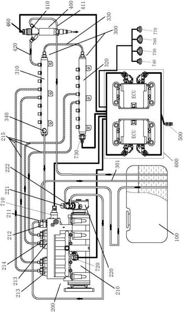
[0038] like figure 1 As shown, the present invention provides a diesel engine high-pressure common rail system, including: a mechanical system and an electronic control system;

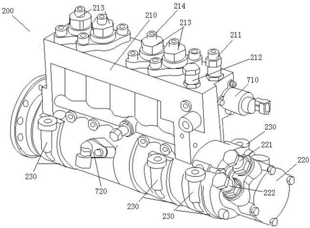
[0039] The mechanical system includes: a high-pressure common rail fuel injection pump 200, a high-pressure common rail pipe 300 and a fuel injector 400; wherein, the structure of the high-pressure common rail fuel injection pump 200 is as follows figure 2 As shown; the high-pressure common rail fuel injection pump 200 includes: a high-pressure pump 210 and a fuel delivery pump 220; the fuel delivery pump 220 is arranged at one end of the high-pressure pump 210, and the other end of the high-pressure pump 210 is connected to the gear of the diesel engine The diesel engine camshaft transmission connection in the tank; the connection ports of the fuel delivery pump 220 include: the fuel oil low-pressure fuel inlet valve 221 of the fuel delivery pump and the fuel low-pressure fuel outlet valve 222 of th...

Embodiment 2

[0050] Figure 4 As shown, in this embodiment, on the basis of Embodiment 1, the high-pressure common rail system of the diesel engine further includes: an oil-water separator 800 and a diesel filter 900; The diesel filter 900 and the fuel low-pressure fuel inlet valve 211 of the high-pressure pump are sequentially connected in series through oil pipes. The invention further provides an oil-water separator and a diesel oil filter for the high-pressure common-rail system of the diesel engine to provide cleaner fuel supply for the high-pressure common-rail system of the diesel engine by way of filtering, and provides strong structural support for the stable operation of the diesel engine.

[0051] preferred, such as Figure 4 As shown, in a preferred technical solution of this embodiment, the electronic control unit is also provided with an OBD fault diagnosis interface 780 . The present invention further provides a powerful structural support for the electronic control system...

Embodiment 3

[0053] Figure 5 As shown, in this embodiment, on the basis of the above embodiments, the camshaft rotation position detection device includes: a fuel injection pump camshaft phase sensor 721 and a camshaft phase gear 722; the camshaft phase gear 722 is fixed on the high pressure pump cam shaft, the setting position of the camshaft phase sensor of the fuel injection pump matches the setting position of the camshaft phase gear; a plurality of camshaft phase teeth are uniformly arranged on the camshaft phase gear; when multiple When the camshaft phase teeth of the fuel injection pump respectively pass through the detection area of ​​the camshaft phase sensor of the fuel injection pump, the camshaft phase sensor of the fuel injection pump feeds back a detection signal.

[0054] In the present invention, the high-pressure pump is equipped with a camshaft rotation position detection device, and the technical effect of detecting the diesel engine speed is also achieved by detecting ...


PUM

PropertyMeasurementUnit
Radiusaaaaaaaaaa

Abstract

The invention relates to a diesel engine high-pressure common rail system which is applicable to V-type diesel engines and provides support for improving diesel engines from the national II standard to the national III standard. The diesel engine high-pressure common rail system structurally comprises a mechanical system and an electric control system. The mechanical system comprises a fuel tank, a high pressure common rail fuel injection pump, a high pressure common rail pipe and fuel injectors. The high pressure common rail pipe comprises a first common rail pipe body and a second common rail pipe body, and main fuel paths of the first common rail pipe body and the second common rail pipe body are connected in series through a common rail fuel pipe. The multiple fuel injectors are arranged and are connected with the main fuel path of the first common rail pipe body or the main fuel path of the second common rail pipe body through second high pressure fuel pipes. The electric control system comprises an electric control unit, sensors and actuators. The electric control unit comprises two ECUs. The diesel engine high-pressure common rail system has the technical advantages that within the service life, the effect that the fuel delivery quantity is doubled and redoubled compared with that of a dual-plunger common rail fuel injection pump can be guaranteed under any working condition, the output fuel quantity of a fuel delivery pump, the flow of a fuel metering valve and the output fuel quantity of a high pressure pump are increased substantially, the maximum common rail pressure can reach 2000 bar, and the continuous working pressure can be kept at 1600 bar.

Description

technical field [0001] The invention relates to the technical field of high-pressure common rail for diesel engines, in particular to a high-pressure common rail system for diesel engines. Background technique [0002] Common rail technology refers to a fuel supply method that completely separates the generation of injection pressure from the injection process in a closed-loop system composed of a high-pressure fuel pump, a pressure sensor and an ECU. The high-pressure fuel pump delivers high-pressure fuel to the public fuel supply pipe. Precise control of the oil pressure in the common oil supply pipe makes the pressure of the high pressure oil pipe independent of the engine speed, which can greatly reduce the variation of the oil supply pressure of the diesel engine with the engine speed, thus reducing the defects of the traditional diesel engine. The ECU controls the fuel injection volume of the injector, and the fuel injection volume depends on the pressure of the fuel r...

Claims


Application Information

Patent Timeline
IPC IPC(8): F02M55/02F02M51/04F02M51/06F02D41/38
CPCF02D41/3845F02M51/04F02M51/06F02M55/025
Inventor 练兵
Owner 常州威曼新能源有限公司
Why Eureka
Try Eureka