
Ultrasonic concrete detection device

A detection device, ultrasonic technology, applied in the direction of measuring device, ultrasonic/sonic/infrasonic generation, using sound wave/ultrasonic/infrasonic to analyze solids, etc., can solve the problem of inability to measure other characteristics of concrete materials, low operating frequency of ultrasonic transducers, The detection device is large in size and other problems, so as to achieve the effect of convenient portability, fast detection speed and performance improvement

Pending Publication Date: 2017-03-22
NANJING UNIV OF INFORMATION SCI & TECH
View PDF8 Cites 6 Cited by
  • Summary
  • Abstract
  • Description
  • Claims
  • Application Information

AI Technical Summary

Problems solved by technology

At present, some conventional ultrasonic non-destructive testing methods widely used in China are focused on manual flaw detection. The detection device is large in size, its operation engineering is relatively complicated, and the detection cycle is relatively long. Relatively speaking, the detection efficiency is relatively low.
[0003] For example, the Chinese patent with the publication number CN204882467U proposes an intelligent concrete ultrasonic detection device, which includes placing the transmitting and receiving transducers on the concrete surface relative to each other, and after transmitting the sound waves, the received sound waves are processed by the device to display data and waveform results, but this Ultrasonic transducers have low operating frequency, poor resolution, single measurement results, and cannot measure other properties of concrete materials such as material, hardness, fatigue, etc.

Method used


Image

  • Ultrasonic concrete detection device
  • Ultrasonic concrete detection device
  • Ultrasonic concrete detection device

Examples


Embodiment Construction

[0027] The present invention will be described in detail below with reference to the accompanying drawings and specific embodiments.

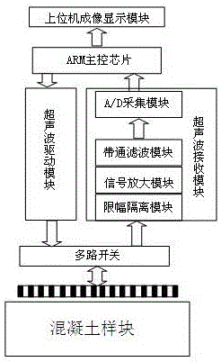
[0028] like figure 1 As shown, an ultrasonic concrete detection device of the present invention includes a host computer imaging display module, an ARM main control chip, an ultrasonic driving module, an ultrasonic receiving module, a multiplex switch and an ultrasonic phased array transducer array.

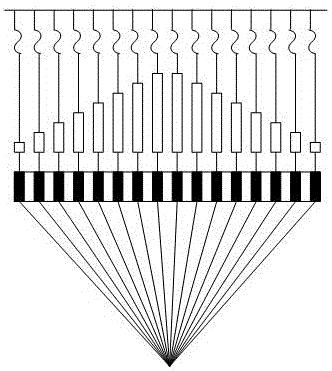
[0029] The ARM main control chip generates an ultrasonic drive signal, and by controlling the multi-way switch, the ultrasonic phased array transducer array transmits and receives the ultrasonic signal generated by the ultrasonic drive module according to a certain delay law. The ultrasonic signal is fed back by the concrete sample block to obtain The echo signal is processed by the ultrasonic receiving module and fed back to the ARM main control chip, and finally displayed by the upper computer imaging display module.

[0030] Wherein, the ultra...


PUM


Abstract

The invention discloses an ultrasonic concrete detection device. The ultrasonic concrete detection device comprises an upper computer imaging display module, an ARM main control chip, an ultrasonic driving module, an ultrasonic receiving module, a multi-way switch and an ultrasonic phased array transducer array, wherein one end of the ARM main control chip is connected with the upper computer imaging display module, and the other end of the ARM main control chip is connected with the ultrasonic driving module and the ultrasonic receiving module, respectively, and the ultrasonic driving module and the ultrasonic receiving module are connected with the ultrasonic phased array transducer array through the multi-way switch. According to the ultrasonic concrete detection device, the disadvantages of relatively large size, low resolution ratio and single detection result of a traditional detection device are overcome; by controlling the ultrasonic phased array transducer array, the high-speed scanning can be realized, the concrete can be effectively penetrated without being damaged by virtue of the high-frequency focusing property of the ultrasonic phased array transducer array, and the properties of a concrete materials can be detected.

Description

technical field [0001] The invention relates to a detection device, in particular to an ultrasonic concrete detection device. Background technique [0002] Among the five conventional nondestructive testing techniques, ultrasonic testing is the most widely used. At present, some conventional ultrasonic nondestructive testing methods widely used in China focus on manual flaw detection. The size of the testing device is relatively large, the operation engineering is relatively complicated, the testing period is relatively long, and the testing efficiency is relatively low. [0003] For example, a Chinese patent with publication number CN204882467U proposes a smart concrete ultrasonic detection device, which includes placing the transmitting and receiving transducers on the concrete surface oppositely, and after transmitting the acoustic waves, the received acoustic waves are processed by the device to display data and waveform results. Ultrasonic transducers have low operatin...

Claims


Application Information

Patent Timeline
IPC IPC(8): G01N29/04G01N29/34
CPCG01N29/04G01N29/341G01N2291/0232
Inventor 张自嘉钱琛邓云霏崔恩隆
Owner NANJING UNIV OF INFORMATION SCI & TECH
Learn More