Power system of combine harvester

A technology of combine harvester and power system, applied in the direction of harvester, transmission element, mechanical equipment, etc., can solve the problems of difficulty in walking, easy to sag, and large space occupied

Active Publication Date: 2017-04-19
JINHUA VOCATIONAL TECH COLLEGE
View PDF5 Cites 6 Cited by
  • Summary
  • Abstract
  • Description
  • Claims
  • Application Information

AI Technical Summary

Problems solved by technology

On the other hand, users have higher and higher requirements for the return on investment of combine harvesters, and the harvest of single-season crops can no longer meet the user's income requirements
[0003] The walking power output mechanism in the power system here is mainly used to realize the walking, braking and steering of the entire combine harvester by driving the crawler belt, but there are currently big problems due to the unreasonable mechanism of the entire walking power output mechanism. When one side When the track brakes, the walking power output mechanism drives it to produce complete sliding friction against the ground when turning, which seriously damages the soil of the paddy field. When it turns, the track on the braking side will cause soil accumulation, resulting in difficulty in turning. And lead to insufficient fuel combustion. At the same time, due to the demand for combine harvesters in the market, under the same chassis aspect ratio, increasing the weight of the whole machine will make steering more difficult. Once the load increases, the resistance of one side of the track increases. It will cause the engine to stal

Method used


Image

  • Power system of combine harvester
  • Power system of combine harvester
  • Power system of combine harvester

Examples


Embodiment 1

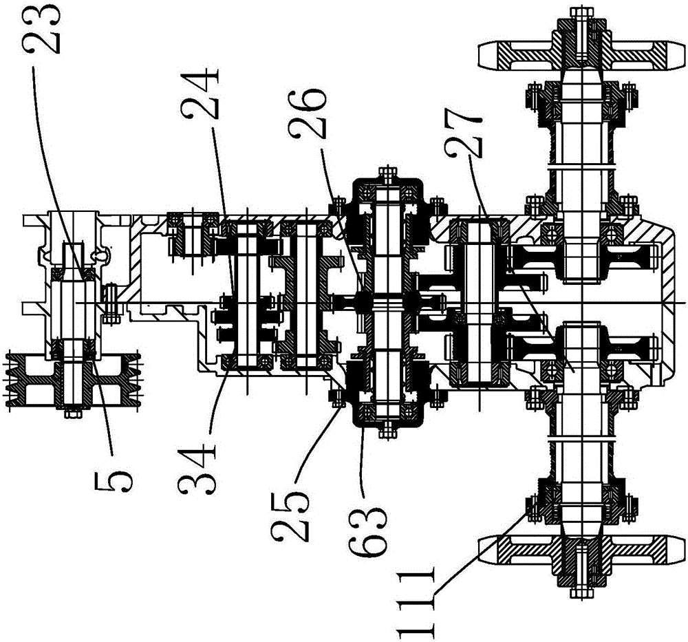
[0087] like image 3 As shown, the power input mechanism of the combine harvester mainly includes a power input shaft 1, an outer casing 2, a power input pulley assembly 3, a continuously variable transmission 4 and a lubrication adjustment assembly 7, and the power input shaft 1 is arranged horizontally and used for rotation, and the outer casing 2 A hollow hole 6 is opened horizontally, and the power input shaft 1 is arranged in the hollow hole 6. The power input pulley assembly 3 is arranged on one end of the power input shaft 1 and is used to connect with an external engine and provide power input. The continuously variable transmission 4 is arranged on the power input shaft. The other end of the rotating shaft 1 is also used to adjust the speed change of the power input rotating shaft 1 .

[0088] The shaft matching mechanism in the power input mechanism 23 is a clearance fit assembly 5, and a clearance fit assembly 5 for adjusting the rotation gap distance of the power i...

Embodiment 2

[0092] Most of the structure of this embodiment is the same as that of Embodiment 1, the difference is that, as Figure 4 As shown, the first clearance fit assembly includes a first rolling bearing 11 and a first transverse clearance elastic member 13, the first transverse clearance elastic member 13 is arranged in the first stepped groove 15, and the two ends of the first transverse clearance elastic member 13 are respectively The function presses on the first rolling bearing 11 and the first stepped groove 15 and is used to adjust the transverse clearance of the first rolling bearing 11. The second clearance fit assembly includes the second rolling bearing 12 and the second transverse clearance elastic member 14. The second transverse clearance elastic The piece 14 is arranged in the second stepped groove 16, and the two ends of the second transverse gap elastic piece 14 respectively press against the second rolling bearing 12 and the second stepped groove 16 and are used to ...

Embodiment 3

[0094] Most of the structure of this embodiment is the same as that of Embodiment 2, the difference is that, as Figure 5 As shown, the clearance fit assembly also includes a longitudinal adjustment bearing 20, which is arranged between the outer casing 2 and the power input shaft 1, and the longitudinal adjustment bearing 20 includes a plurality of alternating rigid layers 22 and gap adjustment layers 21, longitudinally The adjustment bearing 20 includes two gap adjustment layers 21 and three rigid layers 22. The longitudinal adjustment bearing 20 is filled with the gap between the power input shaft 1 and the outer casing 2. The rigid layer 22 here ensures the rotation effect and prevents wear and tear. The gap adjustment layer 21 in the longitudinal adjustment bearing 20 can shrink or expand with the external force, which is equivalent to adjusting the rotation gap between the power input shaft 1 and the outer casing 2, which can prolong the wear life and further improve the ...


PUM


Abstract

The invention belongs to the technical field of agricultural equipment and provides a power system of a combine harvester. The power system is characterized by comprising the following mechanisms: a power input mechanism, a gear shift mechanism, a braking mechanism, a steering and clutching drive mechanism and a walking power take off mechanism, wherein axle fit mechanisms which are used for keeping running clearance distances and fixed positions of all the mechanisms are arranged in the power input mechanism, the gear shift mechanism, the steering and clutching drive mechanism and the walking power take off mechanism. The power system of the combine harvester has the advantages that through the axle fit mechanisms, the stability of a crawler transmission structure is guaranteed, failure and damage are not easy, the reduction of maintenance cost is facilitated, the running speed on smooth pavements and adaptability to complicated field parcels of the combine harvester are improved, the cross-region operational performance of the combine harvester is improved greatly, the wear life can be prolonged, the life is further prolonged, and the reliability is further improved.

Description

technical field [0001] The invention belongs to the technical field of agricultural equipment and relates to a combine harvester, in particular to a combine harvester power system. Background technique [0002] Agricultural machinery refers to various machinery used in crop planting and animal husbandry production, as well as in the primary processing and handling of agricultural and animal products. Agricultural machinery also includes crop harvesting machinery, agricultural transport machinery, etc. At present, driven by factors such as national policy guidance and the transfer of rural labor force, the speed of domestic land transfer has accelerated, the area of ​​a single plot has increased, the roads for machine farming have become wider, and the yield per mu of crops has continued to increase. Users have higher and higher requirements on the working efficiency of combine harvesters. On the other hand, users have higher and higher requirements for the return on invest...

Claims


Application Information

Patent Timeline
IPC IPC(8): A01D69/00A01D69/06A01D69/08A01D69/10A01D69/12F16H3/22F16H37/02
CPCA01D69/002A01D69/06A01D69/08A01D69/10A01D69/12F16H3/22F16H37/02F16H3/30F16H48/19F16H63/32F16H2063/3079F16H2200/0039
Inventor 马广王志明周璇马春晓
Owner JINHUA VOCATIONAL TECH COLLEGE
Why Eureka
Try Eureka