
Flue gas desulphurization waste liquid spray drying treatment apparatus and treatment method thereof

A desulfurization waste liquid and drying treatment technology, which is applied in the direction of gaseous effluent wastewater treatment, spray evaporation, water/sewage treatment, etc., can solve the problems of complex treatment process, small proportion, evaporation and scaling on the plate of the dust collector, etc.

Inactive Publication Date: 2017-04-19
NINGBO UNIV
View PDF7 Cites 3 Cited by
  • Summary
  • Abstract
  • Description
  • Claims
  • Application Information

AI Technical Summary

Problems solved by technology

[0002] One treatment method of flue gas desulfurization waste liquid is chemical treatment, which includes neutralization, sedimentation, flocculation, clarification, sludge treatment and other processes. The chlorine ion content of the desulfurization waste liquid sometimes exceeds the standard
[0003] Another treatment method for flue gas desulfurization waste liquid is the flue waste liquid spray evaporation method, which directly sprays the desulfurization waste liquid into the main flue of the boiler (furnace) to atomize and evaporate the desulfurization waste liquid. There are the following problems: since the main flue of the boiler (furnace kiln) does not have a cavity long enough for the desulfurization waste droplets to evaporate, the desulfurization waste droplets often fall on the heat exchange surface in the main flue to evaporate and scale, or fall on the Evaporation of fouling on the collector plates which could cause improper operation of the heat exchanger or collector involved
In order to solve the technical problems of the flue waste liquid spray evaporation method, the utility model patent "Desulfurization Wastewater Preheating Spray Evaporation System" announced by China (Notice No.: CN204550302U, Patent No.: ZL 201520136263.5) discloses a desulfurization wastewater preheating spray Evaporation system, which is connected with the flue, including dust collector, high-efficiency cyclone separator, waste liquid conveying pipe and waste liquid atomization device, the dust collector is arranged on the flue, and the waste liquid conveying pipe is connected with the high-efficiency cyclone separator , the high-efficiency cyclone separator is connected with the waste liquid atomization device, the waste liquid atomization device is connected with the flue, and the waste liquid preheating device is connected, and the waste liquid preheating device is connected with the high-efficiency cyclone separator and the flue ; The desulfurization wastewater preheating spray evaporation system can increase the temperature of the desulfurization waste liquid by adding a waste liquid preheating device to heat the desulfurization waste liquid before entering the waste liquid spraying device. When the desulfurization waste liquid is sprayed from the waste liquid atomization device , has a higher temperature, and the desulfurization waste liquid with a higher temperature can evaporate more quickly, preventing the non-evaporated desulfurization waste liquid from entering the downstream device, causing damage to the downstream device, but the sensible heat obtained by preheating the desulfurization waste liquid is equivalent to the heat of evaporation Ratio, the ratio is small, the effect of accelerating the evaporation of desulfurization waste liquid is not obvious, the problem of evaporation and scaling of desulfurization waste liquid on the heat exchange surface in the flue, or evaporation and scaling on the plate of the dust collector is still unavoidable

Method used


Image

  • Flue gas desulphurization waste liquid spray drying treatment apparatus and treatment method thereof
  • Flue gas desulphurization waste liquid spray drying treatment apparatus and treatment method thereof
  • Flue gas desulphurization waste liquid spray drying treatment apparatus and treatment method thereof

Examples


Embodiment 1

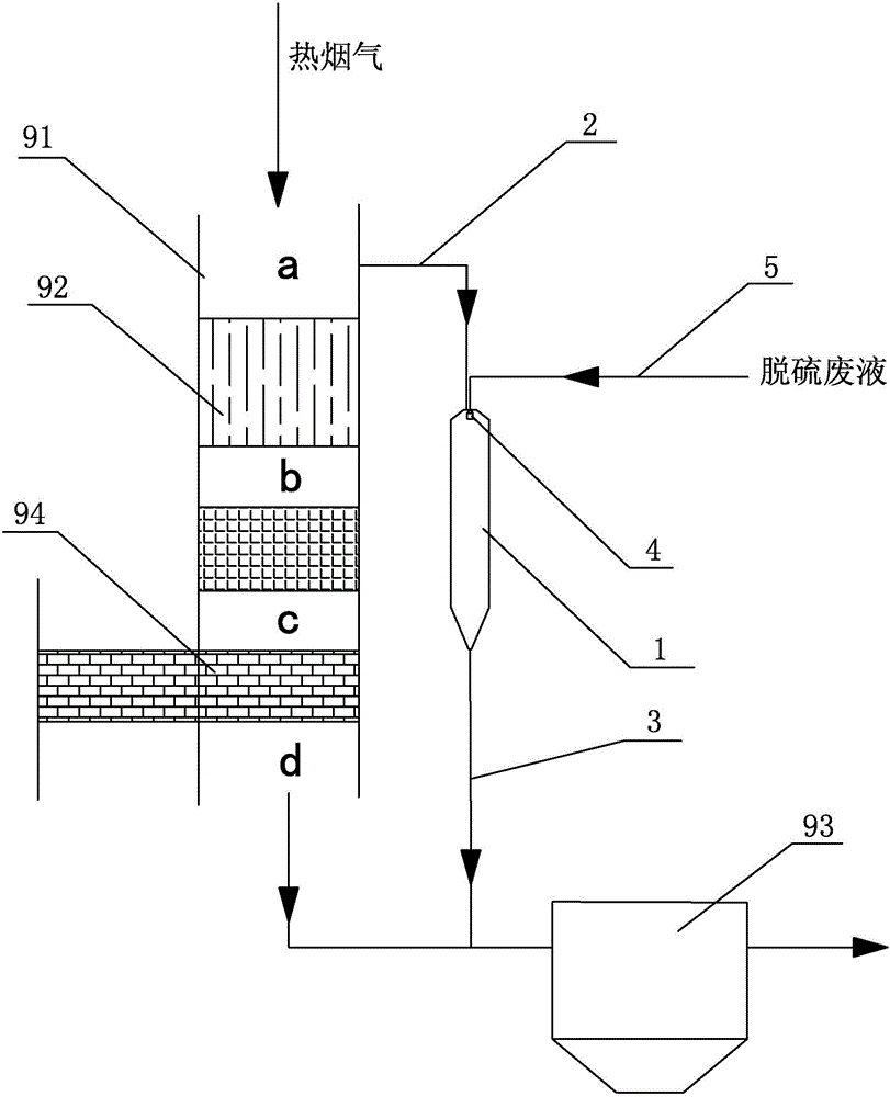
[0021] A kind of flue gas desulfurization waste liquid spray drying treatment device proposed in this embodiment, such as figure 1 As shown, it comprises the spray drying tower 1 that the top has an air inlet and the bottom or the bottom has an air outlet. At the position of the entrance of the economizer 92 provided in the main flue 91 of the kiln) (that is, at the position before the economizer 92, figure 1Middle a place) is communicated with the hot flue gas in the main flue 91 of shunt boiler (furnace kiln), is connected with outlet flue 3 on the gas outlet of spray drying tower 1, and the outlet of outlet flue 3 is connected with boiler (furnace kiln) The downstream of the main flue 91 (that is, the position before the dust collector 93 of the boiler (kiln)) is connected to return the hot flue gas to the main flue 91 of the boiler (kiln), and the top of the spray drying tower 1 A desulfurization waste liquid atomizer 4 is provided, and a desulfurization waste liquid inle...

Embodiment 2

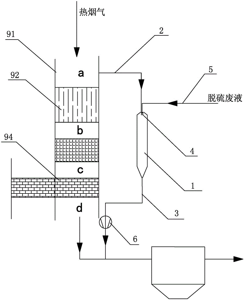
[0023] A flue gas desulfurization waste liquid spray drying treatment device proposed in this embodiment is an improved device after optimizing the flue gas desulfurization waste liquid spray drying treatment device in Example 1. The other structures of the drying treatment device are the same, the only difference is: as figure 2 As shown, an induced draft fan 6 is connected in series on the outlet flue 3 , and the hot flue gas carrying fine powder that enters the outlet flue 3 through the entrance of the outlet flue 3 is transported to the outlet of the outlet flue 3 through the induced fan 6 .

Embodiment 3

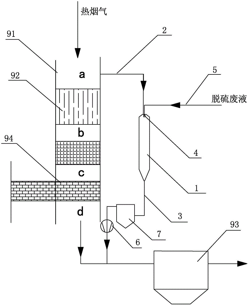
[0025] A flue gas desulfurization waste liquid spray drying treatment device proposed in this embodiment is an improved device after optimizing the flue gas desulfurization waste liquid spray drying treatment device in Example 1. The other structures of the drying treatment device are the same, the only difference is: as image 3 As shown, an auxiliary dust collector 7 and an induced draft fan 6 are sequentially connected in series on the outlet flue 3, and the hot flue gas carrying fine powder that enters the outlet flue 3 through the entrance of the outlet flue 3 is collected by the auxiliary dust collector 7 and carries fine powder. The fine powder in the hot flue gas of powder, the hot flue gas output from the auxiliary dust collector 7 is transported to the outlet of the outlet flue 3 through the induced draft fan 6 . Here, the auxiliary deduster 7 provided can separately collect the fine powder formed by rapid drying of the fine mist of the desulfurization waste liquid, ...


PUM


Abstract

The invention discloses a flue gas desulphurization waste liquid spray drying treatment apparatus and a treatment method thereof. The apparatus comprises a spray drying tower, the gas inlet of the spray drying tower is connected with a gas inlet flue, the inlet of the gas inlet flue communicates with the upstream or the midstream of the main flue of a boiler to shunt hot flue gas in the main flue of the boiler, the gas outlet of the spray drying tower is connected with a gas outlet flue, the outlet of the gas outlet flue communicates with the downstream of the main flue of the boiler to send the hot flue gas to the main flue of the boiler, a desulphurization waste liquid atomizer is arranged in the top of the spray drying tower, and the inlet of the desulphurization waste liquid atomizer is connected with a desulphurization waste liquid inlet tube. The apparatus and the method have the following advantages: the shunted hot flue gas of the boiler is adopted as a heat source, and exchanges heat with fine mist formed through atomizing a desulphurization waste liquid by the desulphurization waste liquid atomizer in the spray drying tower to make the fine mist of the desulphurization waste liquid be rapidly dried in order to form fine powder, so the desulphurization waste liquid is thoroughly eliminated without fouling or corrosion of the main flue of the boiler or a deduster.

Description

technical field [0001] The invention relates to a flue gas desulfurization waste liquid treatment technology, in particular to a flue gas desulfurization waste liquid spray drying treatment device and a treatment method thereof. Background technique [0002] One treatment method of flue gas desulfurization waste liquid is chemical treatment, which includes neutralization, sedimentation, flocculation, clarification, sludge treatment and other processes. The chloride ion content of the desulfurization waste liquid sometimes exceeds the standard. [0003] Another treatment method for flue gas desulfurization waste liquid is the flue waste liquid spray evaporation method, which directly sprays the desulfurization waste liquid into the main flue of the boiler (furnace) to atomize and evaporate the desulfurization waste liquid. There are the following problems: since the main flue of the boiler (furnace kiln) does not have a cavity long enough for the desulfurization waste drople...

Claims


Application Information

Patent Timeline
Patent Type & Authority Applications(China)
IPC IPC(8): B01D1/16C02F1/12C02F1/16C02F103/18
CPCB01D1/16C02F1/12C02F1/16C02F2103/18Y02A20/141
Inventor 杨国华
Owner NINGBO UNIV
Learn More