Multi-beam laser cladding device

A multi-beam and cladding technology, which is applied in the direction of coating, additive manufacturing, and process efficiency improvement, can solve the problems of wire position accuracy changes, complex nozzle structure, and large nozzle volume, so as to reduce the overall size and improve Cladding efficiency, the effect of simple overall structure

Active Publication Date: 2017-04-26
SUZHOU ZHONGKE INNOVATION INST OF LASER INTELLIGENT MFG
View PDF14 Cites 18 Cited by
  • Summary
  • Abstract
  • Description
  • Claims
  • Application Information

AI Technical Summary

Problems solved by technology

However, in the prior art, the following problems exist in the relevant patents that combine cladding and preheating technology: US Patent Application No. US2009 / 0283501A1 discloses that using an independent laser to preheat the workpiece will have the following problems: 1. The structure of the nozzle is very complicated and the cost is high; 2. The nozzle will be very large and cannot enter the narrow space to carry out some cladding work
[0005] The content disclosed in Chinese patent application No. CN201380036006.8 uses an inductance device to preheat the material to be clad, which is completely independent from the cladding work, and there will be the following problems: 1. The structure of the nozzle is very complicated and the cost is high; 2. The volume of the nozzle It will be very large, and it is impossible to enter a small space to carry out some cladding work; 3. The wire is heated inductively in the channel. During the process of leaving the channel and entering the molten pool, the wire loses the heating source, and the temperature on the wire It will change, which will easily lead to changes in the position accuracy of the wire, which will easily affect the surface quality and accuracy of the cladding layer, and even lead to the inability to carry out the cladding work; 4. Inductive heating only heats the wire and does not heat the substrate. Heating only improves the cladding efficiency, but does not really play a role in reducing the thermal stress of the molten layer and reducing defects such as thermal cracks

Method used


Image

  • Multi-beam laser cladding device
  • Multi-beam laser cladding device
  • Multi-beam laser cladding device

Examples


Embodiment Construction

[0030] The specific implementation manners of the present invention will be further described in detail below in conjunction with the accompanying drawings and embodiments. The following examples are used to illustrate the present invention, but are not intended to limit the scope of the present invention.

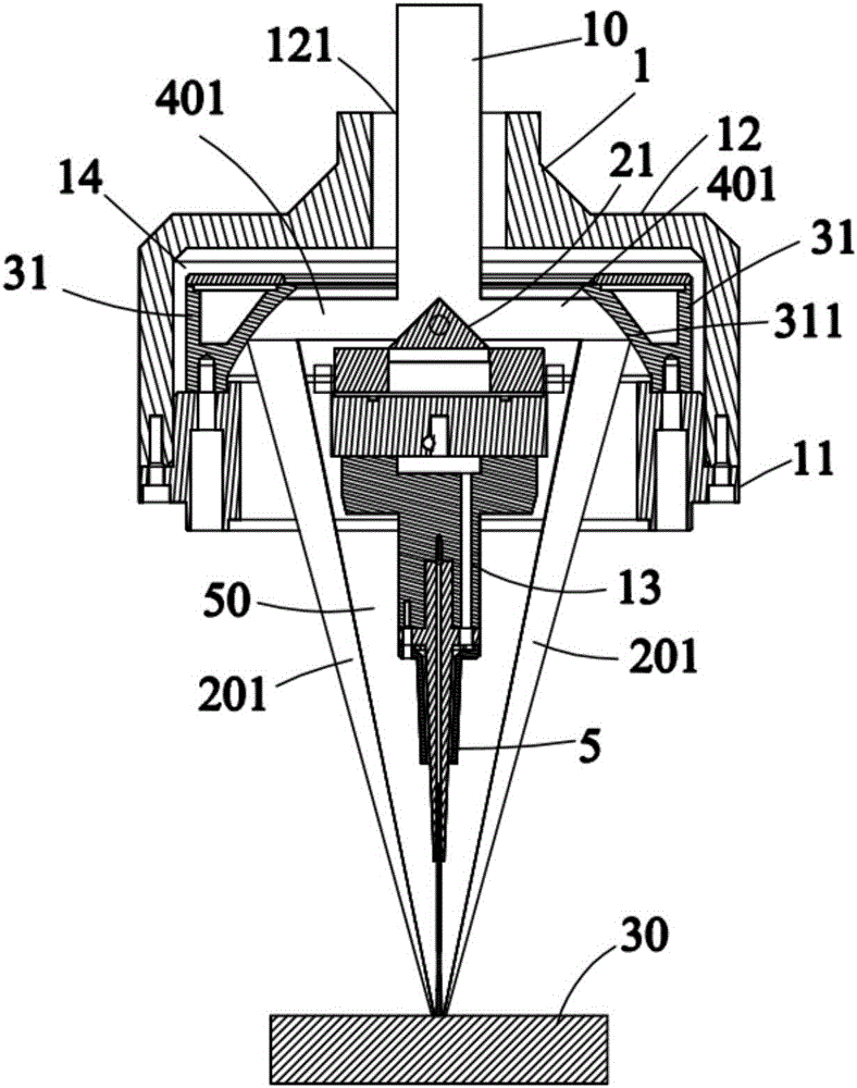
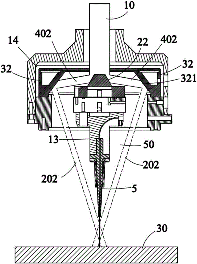
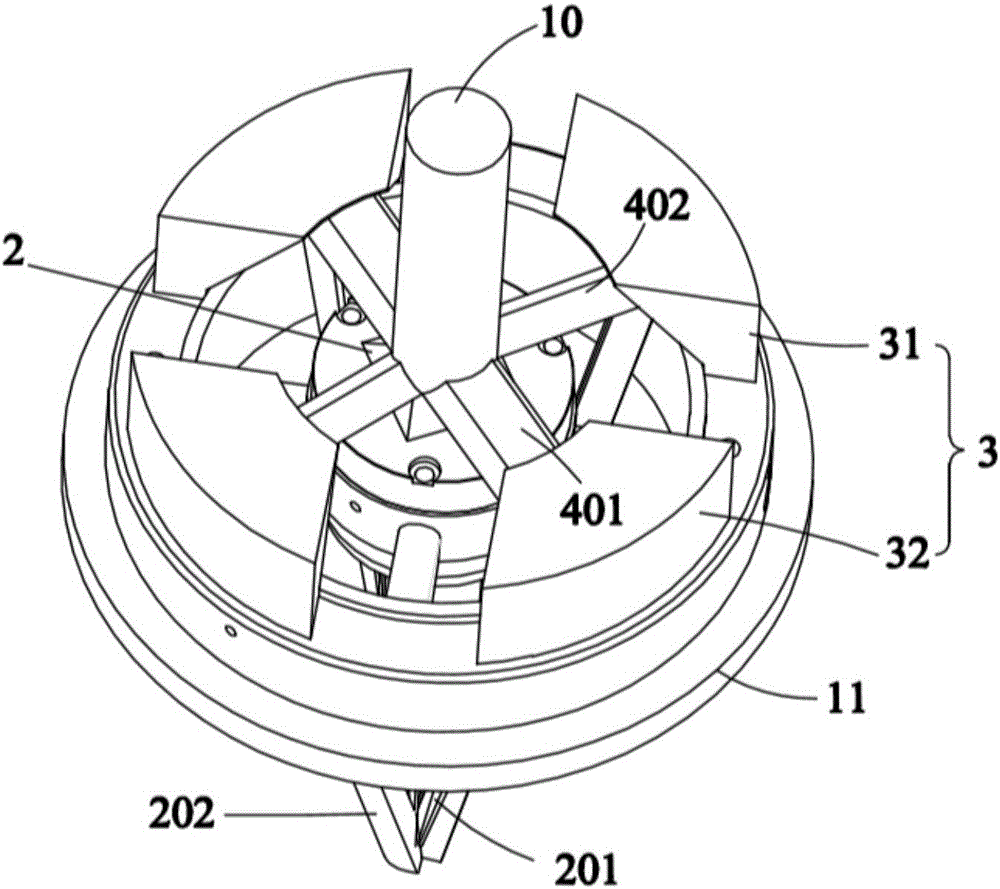
[0031] Please combine Figure 1 to Figure 4 and combine Figure 7, a laser multi-beam cladding device shown in an embodiment of the present invention is used to convert the incident beam 10 to clad the cladding material (not shown) on the substrate 30. In this embodiment, the cladding The covering material is silk. The laser multi-beam cladding device includes a support frame 1 , a beam splitter 2 arranged on the support frame 1 , a reflective focusing assembly 3 and a nozzle 5 located below the reflective focusing assembly 3 . The beam splitter 2 includes two first mirror parts 21 and two second mirror parts 22, and the first mirror parts 21 and the second mirror parts...


PUM


Abstract

The invention relates to a multi-beam laser cladding device comprising a beam splitter and a reflecting-focusing assembly. The beam splitter comprises at least two first mirror surface portions and at least two second mirror surface portions, the first mirror surface portions and the second mirror surface portions are arranged alternately in the circumferential direction of the central axis of the beam splitter, part of incident beams are received and reflected by the first mirror surface portions so as to form first reflected beams, part of the incident beams are received and reflected by the second mirror surface portions so as to form second reflected beams, the first reflected beams and the second reflected beams are reflected in the circumferential direction of the central axis of the beam splitter, and the reflection angle of the first reflected beams is different from the reflection angle of the second reflected beams. The reflecting-focusing assembly comprises a reflecting-focusing lens and a reflector, the first reflected beams are reflected and focused by the reflecting-focusing lens so as to form cladding beams, and the second reflected beams are reflected by the reflector so as to form preheating beams.

Description

technical field [0001] The invention relates to a laser multi-beam cladding device, which belongs to the field of laser additive manufacturing. Background technique [0002] In the advanced laser processing and forming manufacturing technology, there is a key technology, that is, the laser and the molten material are transmitted to the processing and forming position synchronously, and the metal material is continuously, accurately and uniformly put into the processing surface to focus on the scanning movement according to the predetermined trajectory. In the light spot, the precise coupling of optical materials is realized. The material converts light energy and heat energy in the beam, melts instantly and forms a molten pool, and completes the metallurgical process of rapid melting and solidification of the material. [0003] In the prior art, due to the sudden cooling and heating effect of laser cladding, the processing material will have a large degree of overheating an...

Claims


Application Information

Patent Timeline
Patent Type & Authority Applications(China)
IPC IPC(8): B22F3/105C23C24/10B33Y30/00B33Y40/00B33Y10/00
CPCC23C24/103B22F3/003B33Y10/00B33Y30/00B33Y40/00B22F10/00B22F12/44B22F12/53B22F10/25B22F10/362Y02P10/25
Inventor 吉绍山傅戈雁石世宏刘凡鲁键
Owner SUZHOU ZHONGKE INNOVATION INST OF LASER INTELLIGENT MFG
Why Eureka
Try Eureka