Fluid type igniter for gas blaster, and fracturing device
A technology of detonating device and blaster, which is applied in the direction of valve device, blasting cylinder, compressed gas generation, etc. It can solve the problems of low heat release efficiency, uneven mixing of oxidizing agent and reducing agent, time-consuming and labor-consuming, and avoid the occurrence of reaction. Effect
- Summary
- Abstract
- Description
- Claims
- Application Information
AI Technical Summary
Problems solved by technology
Method used
Image
Examples
Embodiment 1
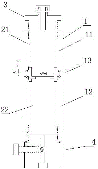
[0063] A fluid type gas blaster detonating device, such as figure 1 As shown, it includes a housing 1 and a filling chamber 2 located in the housing 1. The housing 1 includes a first subsection 11, a second subsection 12 and a coupling head 13. The filling chamber 2 includes a reducing agent filling chamber 21 and An oxidant filling cavity 22, the first subsection 11 and the second subsection 12 respectively contain a reducing agent filling cavity 21 and an oxidizing agent filling cavity 22;
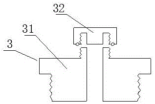
[0064] The two ends of the coupling head 13 are threadedly connected to one end of the first subsection 11 and the second subsection 12 respectively, and a threaded sealing ring 14 is provided at the thread connection between the coupling head 13 and the first subsection 11 and the second subsection 12 , the other ends of the first subsection 11 and the second subsection 12 are respectively connected with a filling nozzle 3 and an inflation mechanism 4;
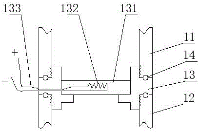
[0065] Such as figure 2 As sh...
Embodiment 2
[0073] The difference with embodiment 1 is: as Figure 5 As shown, the housing 1 is a composite layer tube containing fiber material, and the two ends of the first subsection 11 are respectively sealed and wrapped with a first metal joint 111 and a second metal joint 112, and the second subsection 12 Both ends are respectively sealed and wrapped with a third metal joint 121 and a fourth metal joint 122, the first metal joint 111 is connected to the filling nozzle 3, the fourth metal joint 122 is connected to the inflation mechanism 4, the second metal joint 112 and the third metal joint 121 respectively connects the two ends of the coupling head 13;
[0074] The housing 1 is made of composite layers, the housing 1 includes a base layer 101, a fiber layer 102 and a hardened layer 103, the hardened layer 103 is located on the outer layer of the fiber layer 102, and the base layer 101 is located on the inner layer of the fiber layer 102 ; The base layer 101 is made of polyethyle...
Embodiment 3
[0077] The difference with embodiment 1 is: as Figure 6As shown, the inflation mechanism 4 includes an inflation hole 41, a valve stem 42 and an inflation valve seat 43, the inflation hole 41 runs through the bottom and the top of the inflation valve seat 43, the middle part of the inflation hole 41 is an air lock chamber 411, and the valve stem 42 is threaded The structure is installed in the air-lock chamber 411, and the air-lock chamber 411 is provided with a sealing ball 421, and the sealing ball 421 is located at the bottom of the valve stem 42, which is used to realize the sealing and air-locking of the inflation hole 41, and the valve stem 42 is screwed in Or screw out to control the opening and closing of the inflation hole 41; the inflation valve seat 43 is threadedly connected to one end of the housing 1, the bottom outer wall of the inflation valve seat 43 is provided with a valve seat external thread 44, and one end of the housing 1 is provided with a The valve se...
PUM
| Property | Measurement | Unit |
|---|---|---|
| compressive strength | aaaaa | aaaaa |
| thickness | aaaaa | aaaaa |
| thickness | aaaaa | aaaaa |
Abstract
Description
Claims
Application Information
 - R&D
- Intellectual Property
- Life Sciences
- Materials
- Tech Scout
- Unparalleled Data Quality
- Higher Quality Content
- 60% Fewer Hallucinations
Browse by: Latest US Patents, China's latest patents, Technical Efficacy Thesaurus, Application Domain, Technology Topic, Popular Technical Reports.
© 2025 PatSnap. All rights reserved.Legal|Privacy policy|Modern Slavery Act Transparency Statement|Sitemap|About US| Contact US: help@patsnap.com


