QKD system sending terminal based on phase modulation light source, receiving terminal, QKD system and method thereof

A phase modulation and receiving-end technology, applied in the field of quantum communication, can solve problems such as limitations of system structure integration, high half-wave voltage, system structure and control complexity, etc., to achieve efficient quantum key distribution, simplify structure and control, increase The effect of controlling difficulty

Inactive Publication Date: 2017-04-26
ZHEJIANG SHENZHOU QUANTUM NETWORK TECH CO LTD
View PDF4 Cites 26 Cited by
  • Summary
  • Abstract
  • Description
  • Claims
  • Application Information

AI Technical Summary

Problems solved by technology

[0007] The BB84 protocol quantum key distribution system using the phase modulation light source in the prior art does not avoid the use of the phase modulator at the receiving end, and the actual system structure and performance are still affected by the phase modulator
The BB84 protocol quantum key distribution system using the phase modulation light source in the prior art does not consider the complex problem of pulse intensity modulation, which has limitations on the integration of the system structure
In the quantum key distribution system, the intensity modulator and the phase modulator both need complex drive control circuits, resulting in the complexity of the system structure and control, and the intensity modulator needs to control the bias point at all times, which is difficult to achieve in practice; intensity modulation Both the phase modulator and the phase modulator also require a higher half-wave voltage, which not only consumes energy but also limits the high-speed codec application of the system
The decoy state scheme of pulse intensity modulation is a source-side attack defense scheme commonly used in QKD systems, so the existing technology inevitably faces the complex problem of pulse intensity modulation

Method used


Image

  • QKD system sending terminal based on phase modulation light source, receiving terminal, QKD system and method thereof
  • QKD system sending terminal based on phase modulation light source, receiving terminal, QKD system and method thereof
  • QKD system sending terminal based on phase modulation light source, receiving terminal, QKD system and method thereof

Examples


Embodiment 1

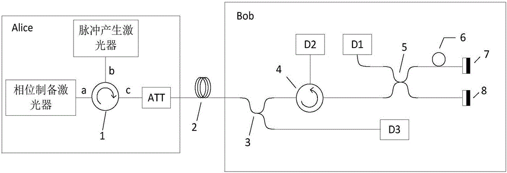
[0044] Such as figure 1 As shown, this embodiment is based on the QKD system of the phase-time unbalanced base vector coding of the phase-modulated light source, including a sending end (Alice) and a receiving end (Bob).

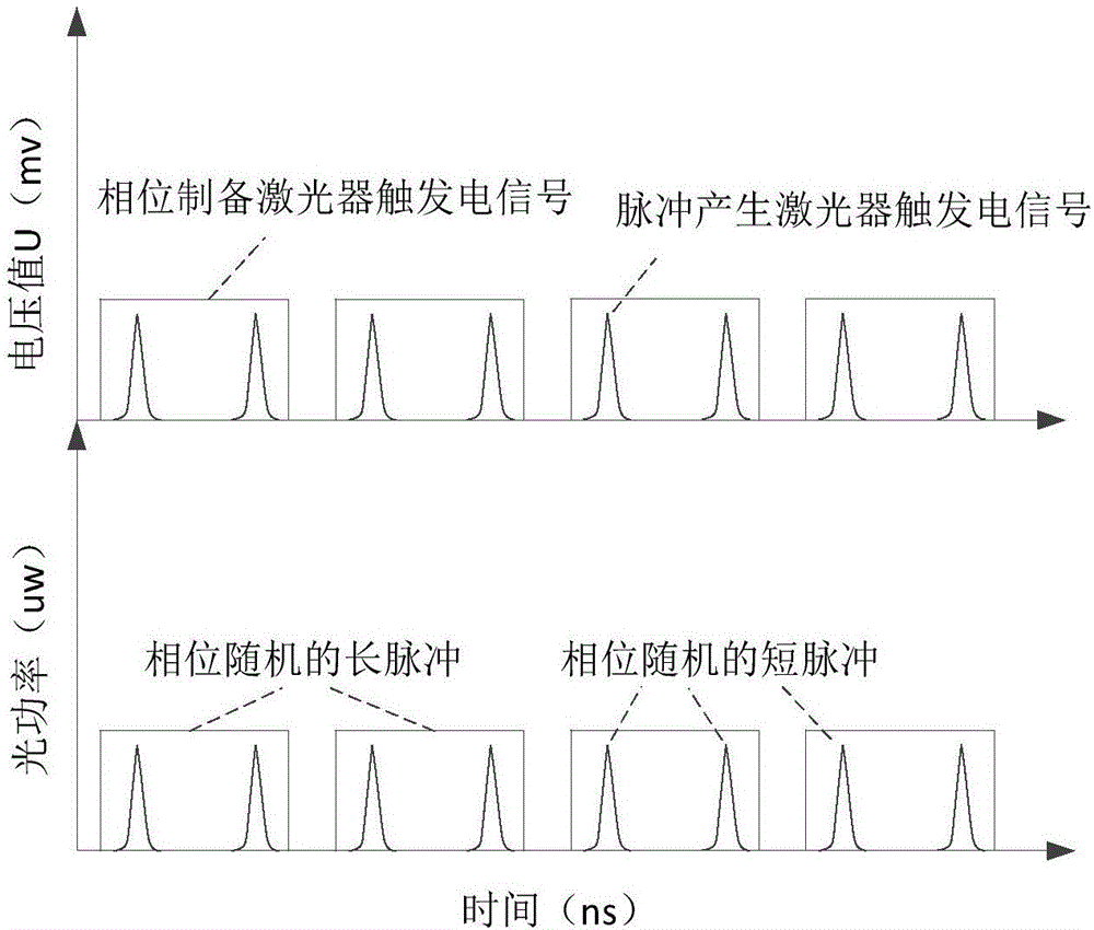
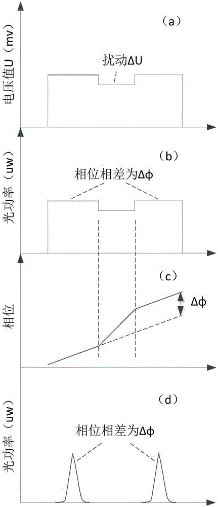
[0045] Alice includes a phase modulation light source and an attenuator (ATT). The phase modulation light source specifically includes a phase preparation laser, a pulse generation laser, and a fiber circulator 1 (optical devices such as isolators are not shown in the figure). In this embodiment, the phase modulation light source can be used Realistic lighting, phase encoding, and time encoding.

[0046] The optical pulse output by the phase preparation laser enters the fiber circulator 1 through the a port, and is injected into the pulse generating laser through the b port, and the optical pulse output by the pulse generating laser is output from the c port through the optical fiber circulator through the port b, that is, the c port is used as phase modulat...

Embodiment 2

[0068] The security proof of quantum key distribution in Embodiment 1 is applicable to the case of single photon, and it is difficult to generate a single photon source in practice, so the weakly coherent light emitted by the phase modulation light source and attenuated to the single photon level by the intensity attenuator ATT is used to generate replace. In addition to the single-photon component, the light pulse emitted by the weakly coherent light source also has a multi-photon component. An eavesdropper can use the multi-photon component to carry out a photon number separation (PNS) attack. The idea of ​​decoy state is proposed to resist the photon number separation (PNS) attack. In order to detect the attack of the eavesdropper, Alice randomly emits light pulses of different intensities, in which the proportions of single photons and multi-photons are different. The eavesdropper cannot distinguish which intensity of light pulse Alice uses, so he cannot adapt to the pass ...

Embodiment 3

[0101] see Figure 7 , this embodiment replaces the optical fiber Michelson interferometer structure in Bob with the optical fiber Mach-Zehnder interferometer structure. The short pulse sequence arriving at Bob is divided into two paths by the fiber beam splitter 9 with any beam splitter ratio, and one path enters the single photon detector D3, which is the same as the above two embodiments, the detection of the time base vector is completed, and the other path enters the optical fiber splitter D3. Beamer 10.

[0102] The fiber splitter 10 with the splitting ratio of 50 / 50, the fiber splitter 11 with the splitting ratio of 50 / 50, and the fiber delay line 12 constitute the unequal-arm Mach-Zehnder interferometer structure of optical pulse differential delay. In order to realize the interference of two pulses before and after in the short pulse sequence, the setting of the fiber delay line 12 at this time is to realize the differential delay of a short pulse interval.

[0103]...


PUM


Abstract

The invention discloses a QKD system sending terminal based on a phase modulation light source, a receiving terminal, a QKD system and a method thereof. By using the QKD system based on the phase modulation light source, at the sending terminal, the phase modulation light source is adopted; and through X basis vector phase coding and Z basis vector time coding modes, a light pulse pair is coded and then the light pulse pair is sent to the receiving terminal. In the invention, the phase modulation light source is used and a low half-wave voltage is possessed so that energy is saved and a possible is provided for a high speed application of the system; and a bias point problem of an intensity modulator does not need to be considered.

Description

technical field [0001] The invention relates to the field of quantum communication, in particular to a QKD system sending end and receiving end based on a phase modulation light source, and a QKD system and method. Background technique [0002] The encoding system based on phase modulation is one of the main types of quantum key distribution (QKD) experimental systems. Because of the strong anti-interference ability of photon phase modulation in optical fiber transmission, it has been widely used. Coding systems based on phase modulation mainly include double unequal arms Mach-Zehnder interferometer system, Michelson interferometer "plug and play" system and Sagnac ring system. The main way to achieve phase modulation of photons is external modulation, by applying an electric field to the phase modulator of some electro-optic materials to change the refractive index of the material, so as to change the optical phase. Commonly used phase modulators are those based on LiNbO3 ...

Claims


Application Information

Patent Timeline
Patent Type & Authority Applications(China)
IPC IPC(8): H04B10/548H04B10/70
CPCH04B10/548H04B10/70
Inventor 富尧王真真
Owner ZHEJIANG SHENZHOU QUANTUM NETWORK TECH CO LTD
Why Eureka
Try Eureka