Garbage incineration fume ultralow emission purifying system

A waste incineration and purification system technology, applied in the direction of gas treatment, chemical instruments and methods, combined devices, etc., can solve the problems of low deacidification efficiency, limited pollutant removal effect, and difficulty in meeting emission requirements, etc., to achieve improved Remove the effect of efficiency

Pending Publication Date: 2017-05-10
SHANGHAI SUS ENVIRONMENT
View PDF5 Cites 31 Cited by
  • Summary
  • Abstract
  • Description
  • Claims
  • Application Information

AI Technical Summary

Problems solved by technology

The deacidification efficiency of the three deacidification processes is different: the dry process is simple, low in investment, and easy to operate and maintain, but the deacidification efficiency is relatively low; the semi-dry process has high deacidification efficiency and low investment and operation costs. No waste water is generated; wet deacidification is the most efficient, but subsequent waste water treatment is required
[0005] At present, the flue gas purification system of waste incineration power plants is mainly based on the process of semi-dry deacidification + activated ca

Method used


Image

  • Garbage incineration fume ultralow emission purifying system

Examples


Embodiment 1

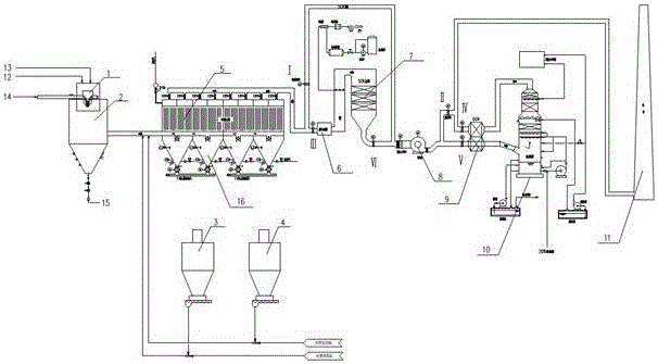
[0044] A waste incineration flue gas ultra-low emission system, its structure diagram is as follows figure 1 As shown, including SNCR denitrification device (not shown in the schematic diagram, which belongs to furnace denitrification), semi-dry reaction tower 2, slaked lime injection device 3, activated carbon injection device 4, bag filter 5, steam heater 6, SCR reactor 7. Induced fan 8, flue gas / flue gas heat exchanger 9, wet scrubber 10, chimney 11;

[0045]The upper part of the semi-dry reaction tower 2 is equipped with a rotary spraying device 1, which is connected with a lime slurry pipeline 12 and an atomizing cooling water pipeline 13, and the inlet 14 of the flue gas is set under the rotary spraying device 1, and the bottom is provided with a discharge port 15. There is a flue gas outlet on the side wall;

[0046] A slaked lime injection device 3 and an activated carbon injection device 4 are connected to the flue between the flue gas outlet on the side wall of the ...

Embodiment 1

[0064] That is to say, the flue gas combination treatment process of "semi-dry deacidification + activated carbon injection adsorption of dioxin + bag filter" is adopted in the existing technology, the pollutant discharge meets the standard requirements, and the smoke content is 80mg / m 3 , sulfur dioxide 260 mg / m 3 , hydrogen chloride 75 mg / m 3 , the average value of mercury and cadmium is 0.15 mg / m 3 , the average value of lead determination is 1.6 mg / m 3 , Dioxins 1.0ngTEQ / m 3 , in which dust, dioxins and acid substances failed to meet the EU 2000 emission standards.

[0065] By comparing the above application implementation example 1 with the comparison implementation example 1, it can be seen that a kind of waste incineration flue gas ultra-low emission purification system of the present invention, its treatment effect has been greatly improved compared with the prior art, and the smoke content and sulfur dioxide emissions are reduced by 1 / 8 and 1 / 26 times of the exist...


PUM


Abstract

The invention discloses a garbage incineration fume ultralow emission system. A garbage incineration fume purifying treatment device comprises an SNCR (selective non-catalytic reduction) device, a semi-dry type reaction tower, a slaked lime spraying device, an activated carbon spraying device, a bag type deduster, a steam heater, an SCR (selective catalytic reduction) reaction tower, a fume/fume heat exchanger, a wet type scrubbing tower, an induced draft fan and a chimney. The low-temperature fume after washing is performed with heat exchange in the fume/fume heat exchanger, heated, and exhausted out of the chimney. The garbage incineration fume purifying treatment device has the advantage that the emission of the fume is superior to the European Union 2000 standard.

Description

technical field [0001] The invention relates to an ultra-low emission system for waste incineration flue gas. Background technique [0002] Garbage incineration can maximize the reduction, harmlessness and recycling of garbage, but incineration will inevitably bring secondary pollution. The flue gas produced by garbage incineration contains a large number of environmentally harmful substances such as acid gases , nitrogen oxides, dust, dioxins, heavy metals, etc., so it is necessary to thoroughly purify the flue gas generated by waste incineration before it is discharged into the atmosphere, so as to minimize its impact on the surrounding environment. [0003] The emission control of dust generated during waste incineration can be achieved through several methods such as electrostatic separation, filtration, centrifugal sedimentation, and wet washing. Common equipment includes electrostatic precipitators, bag filters, and Venturi scrubbers. Venturi dust collectors have high...

Claims


Application Information

Patent Timeline
IPC IPC(8): B01D53/75B01D53/56B01D53/50B01D53/68B01D53/64B01D53/70B01D50/00
CPCB01D53/50B01D53/56B01D53/64B01D53/68B01D53/70B01D53/75B01D2258/0291B01D2257/2047B01D2257/2045B01D2257/602B01D50/60
Inventor 龙吉生白力劳云枫冯淋淋章文锋刘露孙中涛刘焕联
Owner SHANGHAI SUS ENVIRONMENT
Why Eureka
Try Eureka