
Electron Beam Assisted Gas Phase Crosslinking Method

A gas-phase crosslinking and electron beam technology, which is applied in physical treatment, fiber treatment, textiles and papermaking, etc., can solve the problems of difficulty in uniform crosslinking and low production efficiency, and achieve high production efficiency, short crosslinking time and high efficiency. high effect

Active Publication Date: 2019-06-21
NAT UNIV OF DEFENSE TECH
View PDF7 Cites 0 Cited by
  • Summary
  • Abstract
  • Description
  • Claims
  • Application Information

AI Technical Summary

Problems solved by technology

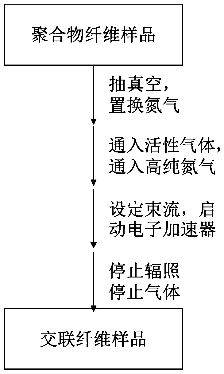
[0005] The purpose of the present invention is to provide an electron beam-assisted gas phase crosslinking method suitable for polymer fibers, which solves the problems of low production efficiency and difficulty in uniform crosslinking of existing electron beam crosslinking technology and gas phase crosslinking technology

Method used


Image

  • Electron Beam Assisted Gas Phase Crosslinking Method
  • Electron Beam Assisted Gas Phase Crosslinking Method
  • Electron Beam Assisted Gas Phase Crosslinking Method

Examples


Embodiment 1

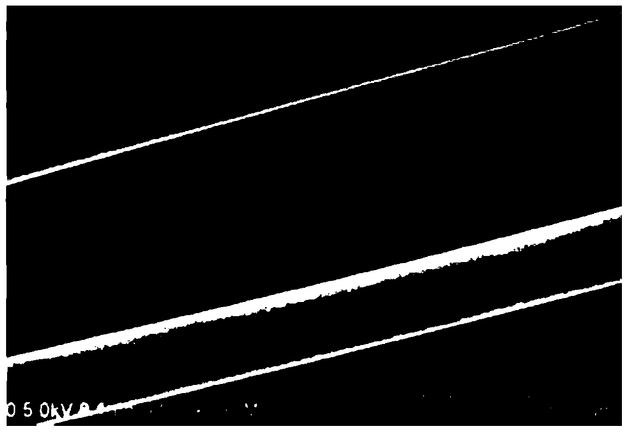
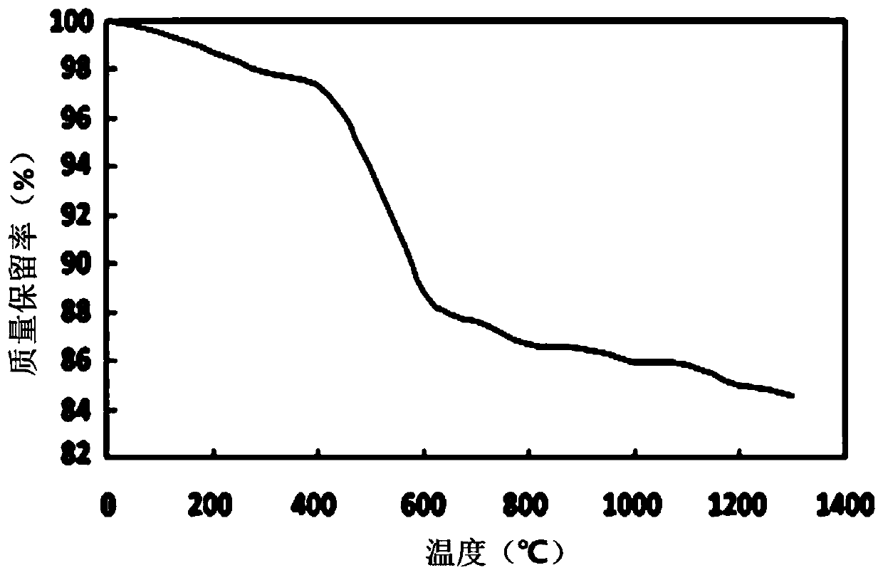
[0019] (1) With 100 grams of polycarbosilane fiber samples, the diameter of the fiber filament is 14 microns, vacuumize and replace high-purity nitrogen, and repeat twice; (2) feed 1,3-butadiene and high-purity nitrogen respectively, 1 , the flow rate of 3-butadiene is 300L / h, and the flow rate of high-purity nitrogen gas is 300L / h; (3) the polycarbosilane fiber rotates in the device under the bundle, and the rotation speed is 5rad / min; (4) start the electron accelerator, the beam The current density is 1kGy / s, the irradiation is 3h, the cumulative irradiation dose is 10.8MGy, and the irradiation is stopped. The cross-linked fiber gel content reaches 95%, the oxygen content is 0.8wt%, and the thermal weight loss at 1000°C in nitrogen is 16% (attached figure 2 ), the micrographs of the crosslinked fiber show that the surface and interface are smooth and dense (attached image 3 ).

Embodiment 2

[0021] (1) Vacuumize 100 grams of polysilazane fiber samples with a fiber filament diameter of 18 microns to replace high-purity nitrogen, and repeat twice; (2) feed dichlorosilane and high-purity nitrogen respectively, with a flow rate of 100 L / h, the flow rate of high-purity nitrogen gas is 500L / h; (3) the polycarbosilane fiber rotates in the device under the beam, and the rotation speed is 10rad / min; (4) start the electron accelerator, the beam density is 0.5kGy / s, and the irradiation After 5 hours, the cumulative radiation dose was 9MGy, and the radiation was stopped. The cross-linked fiber has a gel content of 91%, an oxygen content of 1.2wt%, and a thermal weight loss of 13% at 1000°C in nitrogen.

Embodiment 3

[0023] (1) Take 100 grams of polyborosilazane fiber samples, the diameter of the fiber filament is 15 microns, vacuumize and replace high-purity nitrogen, and repeat twice; (2) feed dichlorosilane and high-purity nitrogen respectively, with a flow rate of 100L / h, the flow rate of high-purity nitrogen gas is 300L / h; (3) the polycarbosilane fiber rotates in the device under the beam, and the rotation speed is 20rad / min; (4) start the electron accelerator, the beam density is 1.5kGy / s, and the radiation After 2 hours of irradiation, the cumulative irradiation dose was 10.8MGy, and the irradiation was stopped. The gel content of the cross-linked fiber reaches 94%, the oxygen content is 1.5wt%, and the thermal weight loss at 1000°C in nitrogen is 15%.


PUM


Abstract

The invention provides an auxiliary gas-phase cross-linking method of electron beams. The method comprises the following steps: (1) loading a polymer fiber sample in an under-beam apparatus, vacuumizing, replacing high-purity nitrogen, and repeating twice; (2) respectively introducing active gas and high-purity nitrogen, wherein a ratio of the high-purity nitrogen flow to the active gas flow is (1 to 1) to (1 to 5); (3) rotating the polymer fibers in the under-beam apparatus at a rotation speed of 5 to 20 rad / min; and (4) starting an electron accelerator, wherein the beam density is 0.5 to 2 kGy / s, and stopping when the accumulative radiation amount is more than 8MGy. The cross-linking degree of the polymer fibers can be judged by testing a gel content of a radiation sample; and the ordinary gel content is greater than 90 percent, thus achieving the cross-linking target.

Description

technical field [0001] The invention relates to the technical field of polymer crosslinking, in particular to a gas phase crosslinking method assisted by electron beams of polymer fibers. Background technique [0002] Electron beam irradiation technology is widely used in the field of material cross-linking, for cable cross-linking (application number: CN201110208091.4; invention name: a method for high-energy accelerator electron beam lamination irradiation cross-linking cables), polymer modification (Application No.: CN200710051000.4; Invention Name: Electron Beam Radiation Modification Method of Polylactic Acid and Its Copolymer Composite Materials), Polymer Curing (Application No.: CN201510221030.X; Invention Name: Electron Beam Cured Siliconized Fiber Web material). In the preparation of continuous silicon carbide fibers and continuous silicon nitride fibers by precursor conversion technology, electron beam irradiation crosslinking has been successfully applied. Japan...

Claims


Application Information

Patent Timeline
Patent Type & Authority Patents(China)
IPC IPC(8): D06M10/08D06M10/06D06M14/30D06M101/30
CPCD06M10/06D06M10/08D06M14/30D06M2101/30
Inventor 邵长伟王军王浩简科王小宙苟燕子
Owner NAT UNIV OF DEFENSE TECH
Learn More