Ship waste gas denitration system

An exhaust gas and denitration technology, applied in the field of ship exhaust gas denitration system, can solve the problems of other equipment arrangement, complex structure and large space occupied that affect the movement space of people on board, so as to achieve compact structure, reduce the setting of connecting parts, and shorten the length. Effect

Inactive Publication Date: 2017-05-10
SUNRUI MARINE ENVIRONMENT ENG
View PDF8 Cites 6 Cited by
  • Summary
  • Abstract
  • Description
  • Claims
  • Application Information

AI Technical Summary

Problems solved by technology

However, the existing denitrification equipment has a complex structure and requires a large space, which affects the activity space of people on board and the arrangement of other equipment.

Method used


Image

  • Ship waste gas denitration system

Examples


Embodiment 1

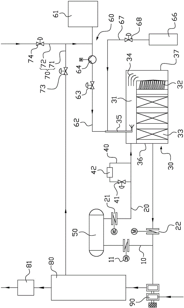
[0040] Carry out exhaust gas denitration treatment on diesel engine of model A: exhaust gas is discharged from the diesel engine to the exhaust gas collecting box, and 1 / 4 of the exhaust gas is drawn from the exhaust gas denitration pipeline to be oxidized and discharged into the denitration reactor. At this time, the urea solution is in the metering pump Under the action, it enters into the urea evaporation chamber and decomposes into ammonia gas. The mixed gas enters the mixer laterally under the action of the baffle for rotating mixing. The mixed gas enters the reaction chamber to undergo catalytic reduction reaction. The reacted gas Enter the turbocharger, then enter the waste heat boiler and muffler, and finally discharge to the atmosphere.

[0041] After the denitration process is over, the flushing water enters the hot water pipeline connected to the waste heat boiler. The water is heated, and the flow of hot water into the cold water pipeline is changed by adjusting the si...

Embodiment 2

[0043] Exhaust gas denitration treatment is performed on diesel engines of model A: exhaust gas is discharged from the diesel engine to the exhaust gas collecting tank, and 1 / 2 of the exhaust gas is drawn from the exhaust gas denitration pipeline to be oxidized and discharged into the denitration reactor. At this time, the urea solution is in the metering pump Under the action, it enters into the urea evaporation chamber and decomposes into ammonia gas. The mixed gas enters the mixer laterally under the action of the baffle for rotating mixing. The mixed gas enters the reaction chamber to undergo catalytic reduction reaction. The reacted gas Enter the turbocharger, then enter the waste heat boiler and muffler, and finally discharge to the atmosphere.

[0044] After the denitration process is over, the flushing water enters the hot water pipeline connected to the waste heat boiler. The water is heated, and the flow of hot water into the cold water pipeline is changed by adjusting t...

Embodiment 3

[0046] Exhaust gas denitrification treatment for diesel engine of model A: Exhaust gas is discharged from the diesel engine to the exhaust gas collecting tank, and 1 / 8 of the exhaust gas is drawn from the exhaust gas denitration pipeline to be oxidized and discharged into the denitration reactor. At this time, the urea solution is in the metering pump Under the action, it enters into the urea evaporation chamber and decomposes into ammonia gas. The mixed gas enters the mixer laterally under the action of the baffle for rotating mixing. The mixed gas enters the reaction chamber to undergo catalytic reduction reaction. The reacted gas Enter the turbocharger, then enter the waste heat boiler and muffler, and finally discharge to the atmosphere.

[0047] After the denitration process is over, the flushing water enters the hot water pipeline connected to the waste heat boiler. The water is heated, and the flow of hot water into the cold water pipeline is changed by adjusting the sixth ...


PUM


Abstract

A ship waste gas denitration system comprises a waste gas direct exhaust pipeline connected with a gas outlet of a waste gas collecting tank through a first valve, a waste gas denitration pipeline connected with the gas outlet of the waste gas collecting tank through a second valve and a denitration reactor connected in the waste gas denitration pipeline, wherein the denitration reactor comprises a urea evaporation chamber, a mixer and a reacting chamber. The urea evaporation chamber is provided with a urea solution spray gun. The mixer is connected with the urea evaporation chamber and the reacting chamber. When the first valve is opened and the second valve is closed, waste gas is exhausted through the waste gas direct exhaust pipeline; and when the first valve is closed and the second valve is opened, the waste gas enters the urea evaporation chamber of the denitration reactor through the waste gas denitration pipeline, then is mixed with urea, enters the reactor through the mixer, and is subjected to denitration and then exhausted. According to the ship waste gas denitration system, the urea evaporation chamber, the mixer and the reacting chamber are combined in the denitration reactor, so that the structure is more compact.

Description

Technical field [0001] The invention relates to the field of atmospheric environmental protection, in particular to a ship exhaust gas denitration system. Background technique [0002] In order to control the emission of NOx from marine exhaust gas collection tanks, the International Maritime Organization passed the amendment to MARPOL 73 / 78 Annex VI “Regulations for the Prevention of Air Pollution from Ships”. The amendment stipulates that from January 1, 2016 onwards The emission control area (Emission Control Area, ECA area) implements Tier III emission standards. This standard establishes a lower nitrogen oxide emission value, which requires denitration treatment of ship exhaust. At present, the most widely used ship exhaust gas collector exhaust gas denitration treatment technology is Selective Catalytic Reduction (SCR). [0003] When using selective catalytic reduction technology to denitrify the exhaust gas, first spray a reducing agent into the exhaust gas at a temperatur...

Claims


Application Information

Patent Timeline
IPC IPC(8): F01N3/20F01N3/28B01D53/94B01D53/56
CPCB01D53/9409B01D2251/2067F01N3/208F01N3/2882F01N2570/14F01N2610/02
Inventor 赵超
Owner SUNRUI MARINE ENVIRONMENT ENG
Why Eureka
Try Eureka