Detonating device for double-supercritical-gas blaster and fracturing device

A supercritical gas and detonation device technology, applied in the direction of valve device, blasting cylinder, compressed gas generation, etc., can solve the problems of high manufacturing cost, low heat release efficiency, combustion or explosion, etc., achieve high mixing uniformity and avoid reaction Effect

Inactive Publication Date: 2017-05-10
郭远军
View PDF1 Cites 0 Cited by
  • Summary
  • Abstract
  • Description
  • Claims
  • Application Information

AI Technical Summary

Problems solved by technology

[0006] The detonating device with the above-mentioned structure has the following problems: 1. The thermal reactants to be filled in the detonating device need to be processed by mixing, mixing, coiling or bagging, and the filling process is time-consuming and labor-intensive. , high manufacturing cost; 2. In the process of filling the detonating device, the oxidant and reducing agent are prone to uneven mixing, resulting in low heat release efficiency; 3. The thermal reaction material needs to be mixed and filled in advance, and the temperature during transportation is high It is easy to cause combustion or explosion, and has a large safety hazard; 4. Due to the delay of the detonating material or other situations, it is easy to appear the situation of squibs, and it is impossible to judge the cause of the squibs, so the safety cannot be eliminated by rowing the squibs. Hidden danger; 5. The existing gas blaster detonation method uses solid activator to burn to generate high temperature, directly conducts heat to liquid carbon dioxide, makes liquid carbon dioxide vaporize and expand, and its heat absorption efficiency of liquid carbon dioxide is low

Method used


Image

  • Detonating device for double-supercritical-gas blaster and fracturing device
  • Detonating device for double-supercritical-gas blaster and fracturing device
  • Detonating device for double-supercritical-gas blaster and fracturing device

Examples


Embodiment 1

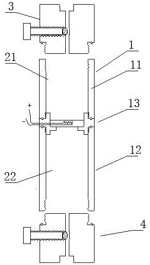
[0061] A dual supercritical gas blaster detonator, such as figure 1 As shown, it includes a housing 1 and a filling chamber 2 located in the housing 1. The housing 1 includes a first subsection 11, a second subsection 12 and a coupling head 13. The filling chamber 2 includes a reducing agent filling chamber 21 and An oxidant filling cavity 22, the first subsection 11 and the second subsection 12 respectively contain a reducing agent filling cavity 21 and an oxidizing agent filling cavity 22;

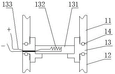
[0062] The two ends of the coupling head 13 are threadedly connected to one end of the first subsection 11 and the second subsection 12 respectively, and a threaded sealing ring 14 is provided at the thread connection between the coupling head 13 and the first subsection 11 and the second subsection 12 , the other ends of the first subsection 11 and the second subsection 12 are respectively connected with a first inflation mechanism 3 and a second inflation mechanism 4; the first inflati...

Embodiment 2

[0070] The difference with embodiment 1 is: as Figure 4 As shown, the housing 1 is a composite layer tube containing fiber material, and the two ends of the first subsection 11 are respectively sealed and wrapped with a first metal joint 111 and a second metal joint 112, the second subsection 12 The two ends are respectively sealed and wrapped with a third metal joint 121 and a fourth metal joint 122, the first metal joint 111 is connected to the first inflation mechanism 3, the fourth metal joint 122 is connected to the second inflation mechanism 4, the second metal joint 112 and the second The three metal joints 121 are respectively connected to the two ends of the connecting head 13;

[0071] The housing 1 is made of composite layers, the housing 1 includes a base layer 101, a fiber layer 102 and a hardened layer 103, the hardened layer 103 is located on the outer layer of the fiber layer 102, and the base layer 101 is located on the inner layer of the fiber layer 102 ; T...

Embodiment 3

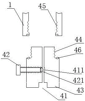
[0074] The difference with embodiment 1 is: as Figure 5 As shown, the second inflation mechanism 4 includes an inflation hole 41, a valve stem 42 and an inflation valve seat 43, the inflation hole 41 runs through the bottom and the top of the inflation valve seat 43, the middle part of the inflation hole 41 is an air lock chamber 411, and the valve stem 42 It is movably installed in the air-lock chamber 411 through the thread structure, and the air-lock chamber 411 is provided with a sealing ball 421, and the sealing ball 421 is located at the bottom of the valve stem 42, which is used to realize the sealing and air-locking of the inflation hole 41, and the valve stem 42 passes through the screw Screw in or out to control the opening and closing of the inflatable hole 41; the inflatable valve seat 43 is threadedly connected to one end of the housing 1, the outer wall of the bottom of the inflatable valve seat 43 is provided with a valve seat external thread 44, and one end of ...


PUM

PropertyMeasurementUnit
compressive strengthaaaaaaaaaa
thicknessaaaaaaaaaa
thicknessaaaaaaaaaa

Abstract

The invention discloses a detonating device for a double-supercritical-gas blaster and a fracturing device. The detonating device comprises a shell and a filling cavity located in the shell. The shell comprises a first segment, a second segment and a connector. The filling cavity comprises a reductant filling cavity body and an oxidant filling cavity body, and the reductant filling cavity body and the oxidant filling cavity body are located in the first segment and the second segment respectively. The two ends of the connector are connected with one end of the first segment and one end of the second segment respectively in a thread sealing mode or a seamless welding mode, the other end of the first segment and the other end of the second segment are connected with a first gas charging mechanism and a second gas charging mechanism respectively, an isolating thermoplastic sheet is installed in the middle of the connector, and an electric heating wire is packaged in the isolating thermoplastic sheet and is led out of the shell through a lead. The detonating device has the advantages of low manufacturing cost, high reaction material mixing uniformity, high heat release efficiency and good transport safety.

Description

technical field [0001] The invention belongs to the field of detonating devices, in particular to a detonating device for double supercritical gas blasters. Background technique [0002] Gas blasting technology is to use the vaporization and expansion of easily vaporized liquid or solid substances to generate high-pressure gas, which makes the surrounding medium expand to do work and cause fragmentation. It has the characteristics of no open flame, safety and high efficiency. [0003] Carbon dioxide gas blasters are typical blasting equipment in gas blasting technology, and are widely used in mining, geological exploration, cement, steel, electric power and other industries, subways and tunnels, municipal engineering, underwater engineering, and emergency rescue. [0004] Existing gas blasters mainly include a vaporization liquid storage pipe and a heating detonator installed in the vaporization liquid storage pipe; the heating detonation device ignites and generates heat to...

Claims


Application Information

Patent Timeline
Patent Type & Authority Applications(China)
IPC IPC(8): F42B3/04F42B3/10F42B3/103F42B3/11F42B3/18C06D5/08C06B47/12C06B47/06C06B47/02C06B27/00F16K15/02F16K24/06
CPCC06B27/00C06B47/02C06B47/06C06B47/12C06D5/08F16K15/02F16K24/06F42B3/045F42B3/10F42B3/103F42B3/11F42B3/18Y02P20/10Y02P20/54
Inventor 郭远军
Owner 郭远军
Why Eureka
Try Eureka