Phase-sensitive optical time-domain reflectometer based on linear frequency-modulation pulse and measurement method of phase-sensitive optical time-domain reflectometer

A linear frequency modulated pulse, phase sensitive light technology, applied in the direction of measuring device, converting sensor output, using optical device to transmit sensing components, etc., can solve the problems of complex demodulation technology and low dynamic performance, achieve simple system structure, improve Dynamic performance, the effect of good linearity

Pending Publication Date: 2017-05-10
ANSHAN REALPHOTONICS TECH CO LTD
View PDF12 Cites 19 Cited by
  • Summary
  • Abstract
  • Description
  • Claims
  • Application Information

AI Technical Summary

Problems solved by technology

[0005] The purpose of the present invention is to provide a chirp-based phase-sensitive optical time-domain reflectometer and measurement method for the problems of low dynamic performance and complex demodulation technology of the current technical solutions, which have the advantages of simple structure, convenient and feasible demodulation technology, and real-time Dynamic distributed phase-sensitive optical time domain reflectometer, which can be applied to real-time dynamic quantitative monitoring of strain, temperature and vibration

Method used


Image

  • Phase-sensitive optical time-domain reflectometer based on linear frequency-modulation pulse and measurement method of phase-sensitive optical time-domain reflectometer
  • Phase-sensitive optical time-domain reflectometer based on linear frequency-modulation pulse and measurement method of phase-sensitive optical time-domain reflectometer
  • Phase-sensitive optical time-domain reflectometer based on linear frequency-modulation pulse and measurement method of phase-sensitive optical time-domain reflectometer

Examples


Embodiment Construction

[0024] The present invention will be described in detail below with reference to the drawings.

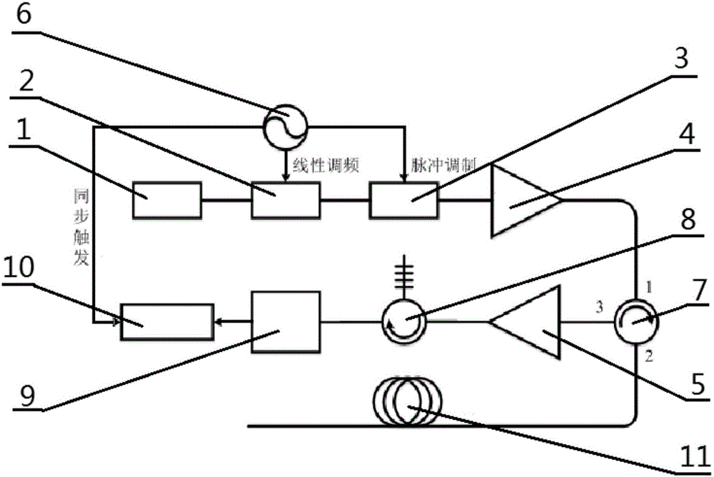
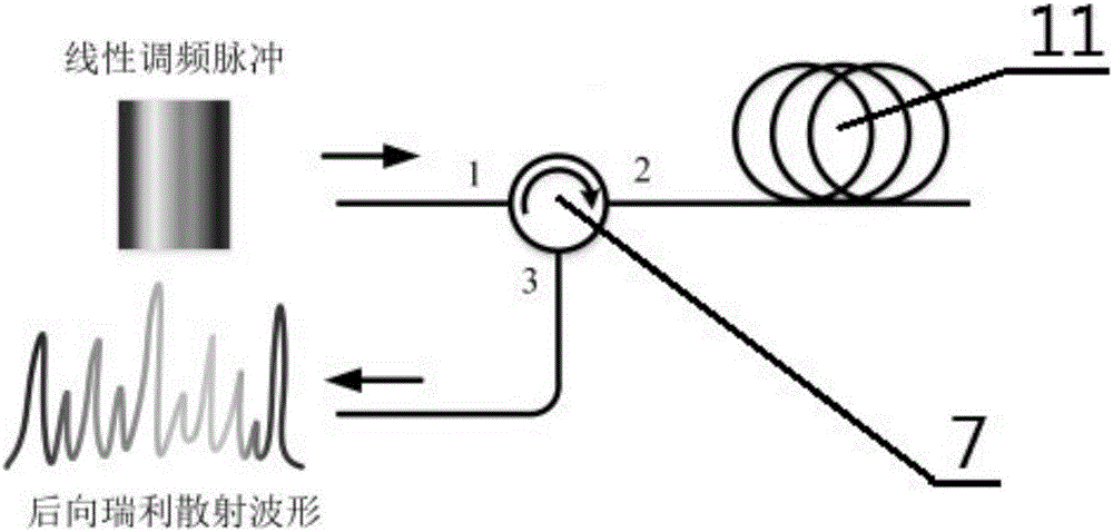
[0025] A phase-sensitive optical time domain reflectometer based on chirp pulse, including laser 1, single sideband modulator SSBM2, acousto-optic modulator AOM3, erbium-doped fiber amplifier EDFAI4, erbium-doped fiber amplifier EDFAII5, arbitrary waveform generator AWG6, Fiber circulator 7, fiber Bragg grating filter FBG8, photodetector 9, data acquisition module 10 and fiber under test 11;

[0026] The output end of the laser 1 is connected to the input end of the single sideband modulator SSBM2, and the narrow linewidth single-frequency continuous laser output from the laser 1 enters the single sideband modulator SSBM2;

[0027] The arbitrary waveform generator AWG6 is located above the single-sideband modulator SSBM2, and the microwave signal whose output frequency of the arbitrary waveform generator AWG6 varies linearly is loaded on the single-sideband modulator SSBM2; the arbitrary ...


PUM


Abstract

The invention relates to a phase-sensitive optical time-domain reflectometer based on a linear frequency-modulation pulse and a measurement method of the phase-sensitive optical time-domain reflectometer. The phase-sensitive optical time-domain reflectometer comprises a laser device, a single side band modulator SSBM, an acoustic optical modulator AOM, an erbium-doped optical fiber amplifier EDFAI, an EDFAII, an arbitrary waveform generator AWG, an optical fiber circulator, a fiber Bragg grating filter FBG, a photoelectric detector, a data collection module and a to-be-measured optical fiber, wherein laser enters the single side band modulator SSBM and is modulated into pulsed light by virtue of the acoustic optical modulator AOM, and the pulsed light is amplified by virtue of the erbium-doped optical fiber amplifier EDFAI and enters the to-be-measured optical fiber through the optical fiber circulator; and a backward Rayleigh scattering signal is output through the optical fiber circulator, a backward Rayleigh scattering optical signal is amplified by virtue of the erbium-doped optical fiber amplifier EDFAII and is detected and converted into an electric signal through the fiber Bragg grating filter FBG, and the data collection module executes data collection and data analysis. By the utilizing linear frequency-modulation pulse, the measurement time is shortened, and the dynamic performance of a system is improved; and the scheme provided by the invention is convenient and feasible, and the structure of the system is relatively simple.

Description

Technical field [0001] The invention relates to a phase sensitive optical time domain reflectometer, in particular to a phase sensitive optical time domain reflectometer based on a chirp pulse and a measurement method. Background technique [0002] Distributed optical fiber sensing technology uses the sensing optical fiber itself as the information transmission medium and sensing unit at the same time, and adopts advanced methods and technologies to realize simultaneous measurement of external physical quantities at hundreds of thousands of points on the optical fiber path, and the optical fiber itself has a volume Small size, light weight, corrosion resistance, electrical insulation, low cost, passive, good windability, etc., which determine that the distributed optical fiber sensing system has incomparable advantages compared with ordinary electrical sensors: corrosion resistance, insulation Good performance, resistance to strong electromagnetic interference; small size and lig...

Claims


Application Information

Patent Timeline
Patent Type & Authority Applications(China)
IPC IPC(8): G01D5/26
CPCG01D5/268
Inventor 董永康陈曦刘昌霞
Owner ANSHAN REALPHOTONICS TECH CO LTD
Why Eureka
Try Eureka