
Magnetically Deflected Electron Beam Evaporation Source

A technology of electron beam evaporation and magnetic deflection, applied in vacuum evaporation coating, ion implantation coating, metal material coating process, etc., can solve the problems of pollution, temperature rise, poor temperature control ability, etc., to avoid mutual pollution , Improve the service life, the effect of uniform temperature distribution

Inactive Publication Date: 2019-08-30
DALIAN JIAOTONG UNIVERSITY
View PDF10 Cites 0 Cited by
  • Summary
  • Abstract
  • Description
  • Claims
  • Application Information

AI Technical Summary

Problems solved by technology

The 180° and 225° deflection evaporation source filament will still be polluted by the evaporator in the crucible, and the effect is not good
Due to the thermal electron bombardment of the inner film material of the crucible, the temperature of the crucible rises sharply (up to 2000 ℃ ~ 6000 ℃), the structure of the traditional cooling mechanism is complex, the heat dissipation effect is not good, and the temperature control ability is poor, which greatly affects the performance of the film.
In addition, the vast majority of magnetic deflection evaporation sources at home and abroad at present use energized magnetic coils to generate deflection magnetic fields. Magnetic coils are energized and generate heat, which is very easy to produce impurities and electrons to pollute the filament and film.
[0006] At present, there is no domestically produced magnetic deflection electron beam evaporation source in China

Method used


Image

  • Magnetically Deflected Electron Beam Evaporation Source
  • Magnetically Deflected Electron Beam Evaporation Source
  • Magnetically Deflected Electron Beam Evaporation Source

Examples


Embodiment Construction

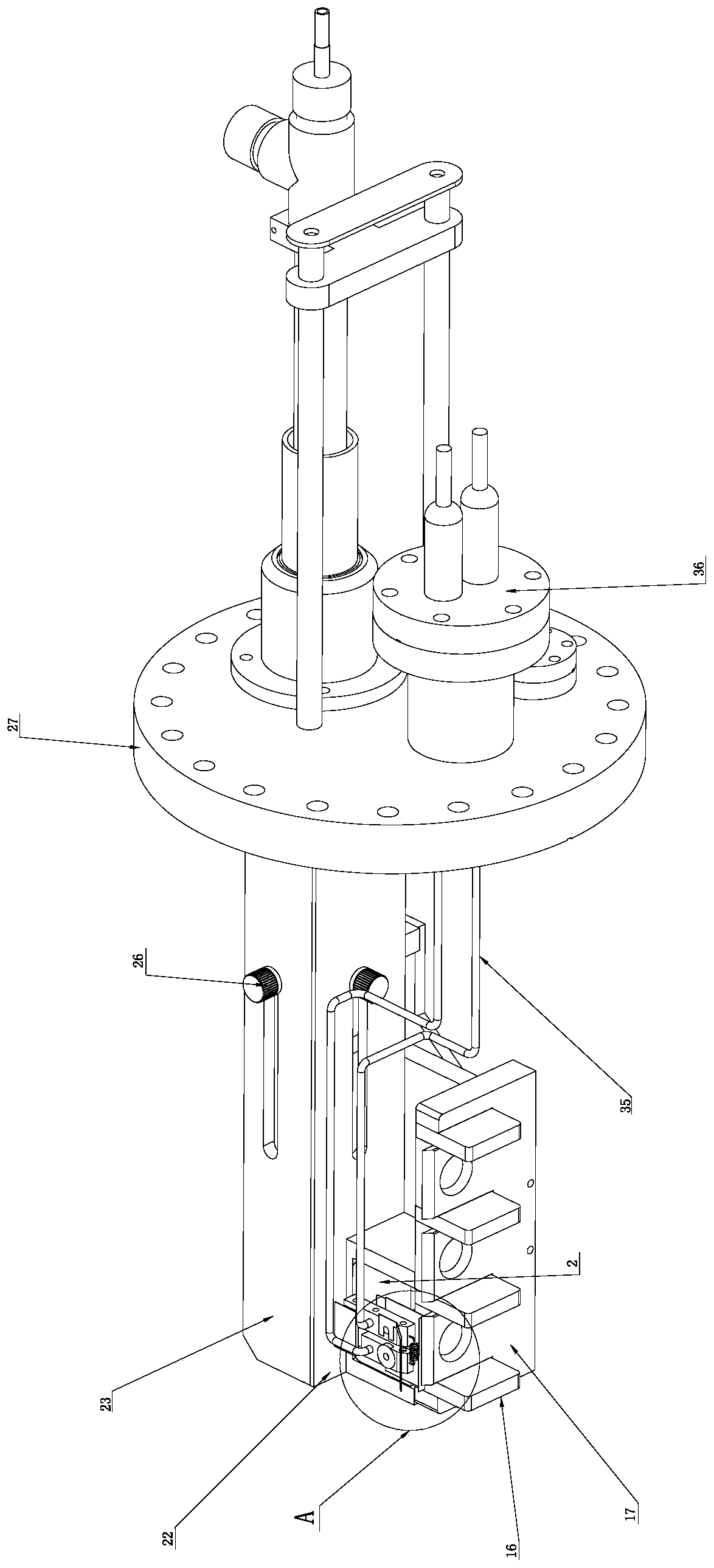
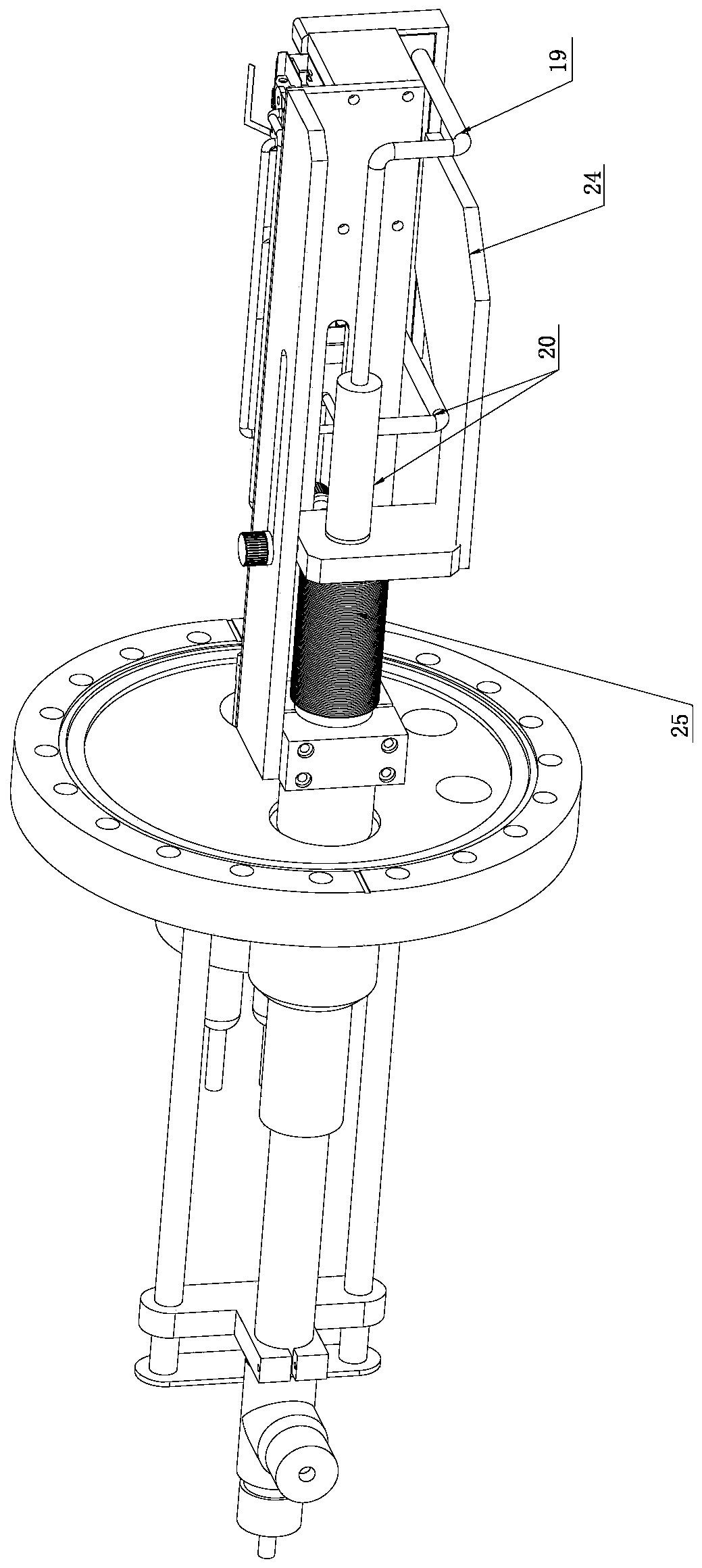
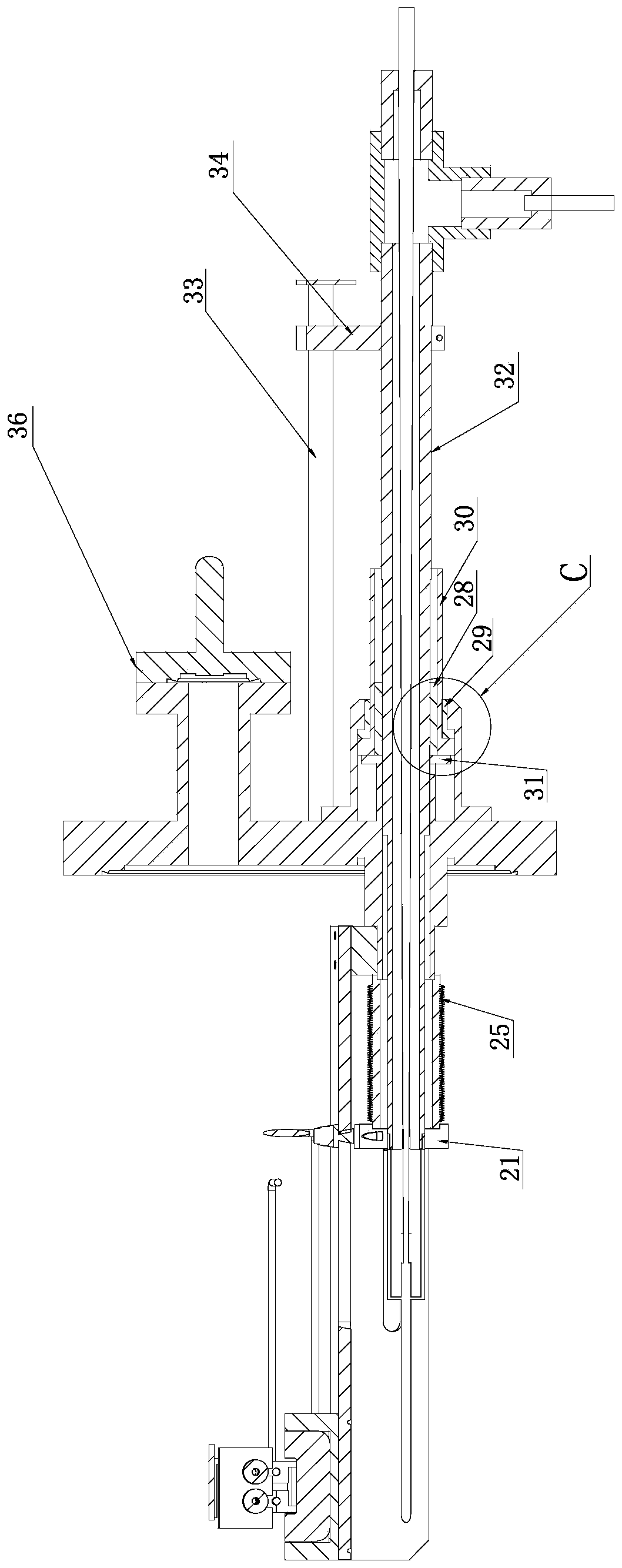
[0040] Such as Figure 1 to Figure 10 A magnetic deflection electron beam evaporation source shown includes: an electron beam generating mechanism, a magnetic deflection assembly, a water-cooled crucible mechanism, a linear transposition mechanism and a working circuit;

[0041] The electron beam generating mechanism includes: filament 8, filament seat A12, filament seat B11, ceramic sheet 10, ceramic seat 9, ceramic seat sleeve 15, support block 13, ceramic column 14, ceramic column protective cover 7, cathode shielding Cover 3, magnet cover 1;

[0042] The filament is fixed on the filament holder A12 and the filament holder B11 by means of screw connection, the filament itself has a certain resistance and generates heat and emits thermal electrons under the condition of negative high voltage and current; the two ceramic sheets 10 are connected by screws fixed in the upper and lower positioning holes of the filament holder A12, the two ceramic holders 9 are located directly ...


PUM


Abstract

The invention discloses a magnetic-deflection electron beam evaporation source which comprises an electron beam generating mechanism, a magnetic deflection assembly, a water-cooled crucible mechanism, a linear transposition mechanism and a working circuit, wherein the electron beam generating mechanism is the core mechanism, and mainly comprises a lamp filament, a lamp filament base, a ceramic sheet, a ceramic base, a supporting block, a ceramic column, a cathode shielding cover and the like. A lamp filament heating mode is adopted to emit hot electrons, and the hot electrons fly to an anode after being accelerated by electric fields between a cathode and the anode; in order to increase evaporation velocity, the cathode shielding cover can be adopted to shield interferences, on electrons emitted by the lamp filament, of magnetic fields generated by a permanent magnet below, and also can be used as a control electrode for regulating the sizes of beam spots; a cooling structure adopts a double-layer water-cooling structure, and a cooling inner barrel in a cooling outer barrel is used for directly feeding cooling water to an oxygen-free copper crucible; and a to-be-evaporated film material is positioned in an oxygen-free copper crucible lining, and the adopted crucible lining can be adopted for enabling temperature distribution of the whole smelting tank to be uniform.

Description

technical field [0001] The invention relates to the field of ultra-high vacuum equipment, in particular to a magnetic deflection electron beam evaporation source. Background technique [0002] In the production process of semiconductor integrated circuits, sensors and solar panels, many structures need to be produced by vacuum coating technology. Therefore, vacuum coating directly determines the quality of products such as semiconductors and solar panels. The research and application of vacuum coating are inseparable from its production equipment, so the research and development of evaporation source is of great significance. [0003] At present, the main vacuum coating technologies at home and abroad include vacuum evaporation coating, vacuum sputtering coating, and vacuum ion coating, among which vacuum evaporation coating is the most widely used. Vacuum evaporation coating technology, that is, in a high vacuum or ultra-high vacuum chamber, the film material (such as met...

Claims


Application Information

Patent Timeline
Patent Type & Authority Patents(China)
IPC IPC(8): C23C14/30
Inventor 郭方准陈欣
Owner DALIAN JIAOTONG UNIVERSITY
Learn More