Welding method for multi-part structure of head injector in thrust chamber of liquid-propellant rocket engine

A liquid rocket, welding method technology, applied in welding equipment, electron beam welding equipment, metal processing equipment, etc., can solve the problems of decreased solder welding force, loss of solder material, and high risk of product scrap, and reduce thermal stress. The effect of concentration, reducing welding deformation and reducing the risk of scrapping

Inactive Publication Date: 2017-05-31
湖北三江航天江北机械工程有限公司
View PDF8 Cites 10 Cited by
  • Summary
  • Abstract
  • Description
  • Claims
  • Application Information

AI Technical Summary

Problems solved by technology

[0004] The traditional welding method of the nozzle of the head injector of the thrust chamber of the liquid rocket engine follows the traditional process method, and the connection between all parts is welded, and there are many welded parts. The process is difficult, and the welding quality is not easy to guarantee, and the reliability is low. The characteristics of this process are mainly reflected in the following aspects:
[0005] 1) The process is complicated, and it is necessary to leave a uniform copper foil solder gap between the welding surfaces during part processing. Before welding, the copper foil solder is evenly filled between the welding surface gaps, which is difficult to process and assemble, and the efficiency is low. Brazing Difficulty, poor welding reliability;
[0006] 2) Welding needs to be completed by heating in a vacuum chamber. If the heating temperature is too high, the brazing filler metal will melt and be lost from the gap between the welding surfaces; Leakage is very difficult, and the product qualification rate is low;
[0007] 3) Once welding leakage occurs, when brazing repair welding is performed again, the previously welded seam may be lost after high temperature and lead to desoldering, and the risk of product scrapping is extremely high

Method used


Image

  • Welding method for multi-part structure of head injector in thrust chamber of liquid-propellant rocket engine
  • Welding method for multi-part structure of head injector in thrust chamber of liquid-propellant rocket engine
  • Welding method for multi-part structure of head injector in thrust chamber of liquid-propellant rocket engine

Examples


Embodiment 1

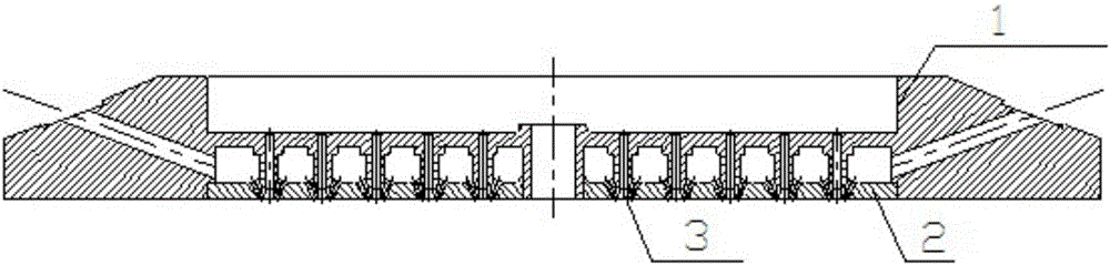
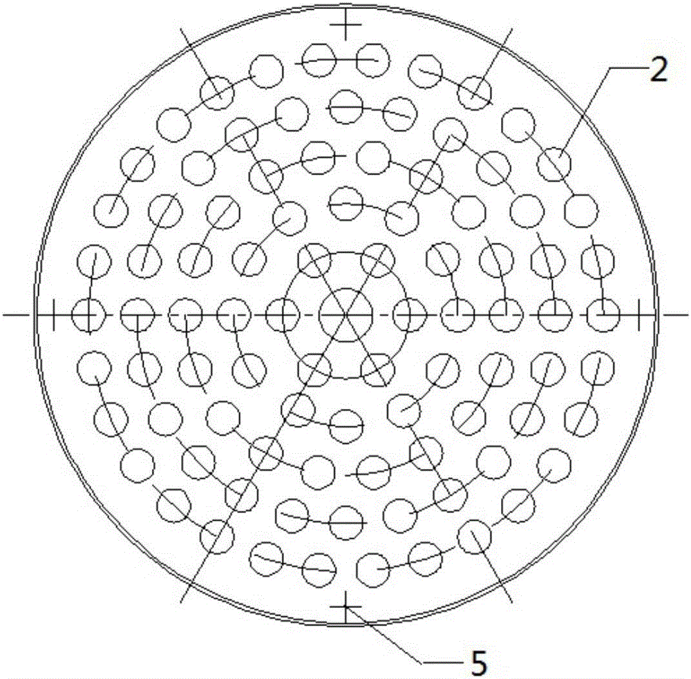
[0040] For a certain type of liquid engine thrust chamber head injector, its structure is as follows figure 1 As shown, the materials are all GH4169, which contains 90 nozzle units, and the 90 nozzle units are arranged in 5 circles in a honeycomb shape. The diameter of the index circle of each circle of nozzle units is Φ38mm, Φ67mm, and Φ96mm from the inside to the outside. . figure 2 , the welding and testing method and process of the injector of the nozzle are as follows:

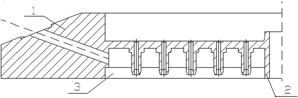
[0041] 1) Process welding parts: process and manufacture welding parts according to the technical requirements of the head injector, including the overall structure of the injector 1 (see attached image 3 ) and round base 2 (see attached Figure 4 ), the circular base 2 takes the center of the circle as a dot and contains 3 groups of multi-circle nozzle unit grooves from the inside to the outside. The shaped base 2 is arranged in a honeycomb shape, and the assembly gap of the parts is less than 0.1mm...

Embodiment 2

[0053] For a certain type of liquid engine thrust chamber head injector, which contains 60 nozzle units,

[0054] The steps of this embodiment and embodiment 1 are basically the same, the difference is:

[0055] 1) In step 5), the vacuum electron beam welding parameters are selected as:

[0056]

[0057] 2) In step 6), the corresponding vacuum electron beam welding parameters are selected as:

[0058]


PUM

PropertyMeasurementUnit
diameteraaaaaaaaaa

Abstract

The invention discloses a welding method for a multi-part structure of a head injector in a thrust chamber of a liquid-propellant rocket engine. According to the method, welding for the head injector in the thrust chamber of the liquid-propellant rocket engine is completed through welded part machining, welding reference machining for nozzle units, welded part pre-treatment, welded part assembly, welded part welding, nozzle unit welding, welding joint detection and drying. According to the method disclosed by the invention, a welding process method for a complex injector structure is optimized to be vacuum electron beam welding adopting a welding method which is more advanced, higher in reliability, higher in welding quality and lower in welding risk from traditional braze welding; and moreover, repair welding is hardly carried out once the traditional braze welding is failed, and local repair welding can be carried out in the vacuum electron beam welding, so that the product scrap risk is lowered.

Description

technical field [0001] The invention relates to the technical field of processing a thrust chamber head injector of a liquid rocket engine, in particular to a welding method for a multi-part structure of a thrust chamber head injector of a liquid rocket engine. Background technique [0002] The liquid rocket engine is the power device of the aerospace vehicle, and the engine thrust chamber is its important component. The thrust chamber is mainly composed of the thrust chamber head, the thrust chamber body and the nozzle extension. The injector is the core component of the thrust chamber head. Its function is to realize the uniform mixing and combustion of fuel and oxidant in a certain proportion. Its working process largely determines the degree of complete combustion of the propellant and the stability of the thrust chamber working process. performance and the reliability of the thermal protection of the thrust chamber wall. [0003] There are many types of injectors in th...

Claims


Application Information

Patent Timeline
Patent Type & Authority Applications(China)
IPC IPC(8): B23K15/04
CPCB23K15/0006B23K15/0033B23K15/0053B23K15/04
Inventor 吴钦初敬生徐明亮徐海升李伟
Owner 湖北三江航天江北机械工程有限公司
Why Eureka
Try Eureka