Automatic hydrogen fluoride feeding device for electrolytic bath and using method of automatic hydrogen fluoride feeding device

A feeding device and hydrogen fluoride technology, applied in the electrolysis process, electrolysis components, etc., can solve problems such as unstable pressure of hydrogen fluoride cylinders, unstable feeding speed control, waste of hydrogen fluoride, etc., to avoid potential safety hazards and increase labor costs, avoid The effect of venting loss and reducing escape

Pending Publication Date: 2017-05-31
昊华气体有限公司
View PDF7 Cites 4 Cited by
  • Summary
  • Abstract
  • Description
  • Claims
  • Application Information

AI Technical Summary

Problems solved by technology

The device has the following disadvantages: (1) The pressure of the hydrogen fluoride steel cylinder is unstable, and the pressure decreases as the weight decreases; (2) The feeding of the electrolyzer is controlled by a needle valve, and the speed of the feeding is unstable; (3) In order to avoid the feeding pipe being The electrolyte is blocked, and the pressure balance solenoid valve is open when not feeding to balance the pressure in the feeding pipe. At the end of the feeding, the hydrogen fluoride remaining in the feeding pipe passes through the H 2 The treatment system is emptied, resulting in waste of hydrogen fluoride

Method used


Image

  • Automatic hydrogen fluoride feeding device for electrolytic bath and using method of automatic hydrogen fluoride feeding device

Examples


Embodiment Construction

[0030] In order to introduce the technical solutions provided by the present invention in more detail, the following will be described in conjunction with the examples.

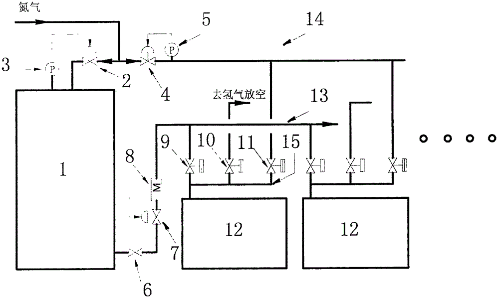
[0031] Such as figure 1 As shown, the hydrogen fluoride automatic feeding device for the electrolytic cell provided by the present invention includes a large-capacity hydrogen fluoride storage tank, a regulating valve, a flow meter, a hydrogen fluoride main pipe, a nitrogen main pipe, a feed pipe and an electrical circuit; the top pipes of the hydrogen fluoride storage tank 1 are connected in sequence Storage tank pressure regulating valve 2 and corresponding storage tank pressure sensor 3, nitrogen pressure regulating valve 4 and corresponding nitrogen pressure sensor 5, nitrogen main pipe 14; the pipeline between storage tank pressure regulating valve 2 and nitrogen pressure regulating valve 4 communicates with nitrogen source One end of the nitrogen replacement valve 11 is connected to the nitrogen main pi...


PUM


Abstract

The invention discloses an automatic hydrogen fluoride feeding device for an electrolytic bath and a using method of the automatic hydrogen fluoride feeding device. The device comprises a hydrogen fluoride storage tank, an adjusting valve, a flow meter, a hydrogen fluoride passing header pipe, a nitrogen header pipe, a passing pipe and an electric circuit. A storage tank pressure adjusting valve, a corresponding storage tank pressure sensor, a nitrogen pressure adjusting valve, a corresponding nitrogen pressure sensor and the nitrogen header pipe are sequentially in pipe connection with the top of the hydrogen fluoride storage tank. A pipeline between the storage tank pressure adjusting valve and the nitrogen pressure adjusting valve communicates with a nitrogen source. One end of a nitrogen replacement valve is connected with the nitrogen header pipe, and the other end of the nitrogen replacement valve is connected with the passing pipe. A hydrogen fluoride outlet in the bottom of the hydrogen fluoride storage tank is sequentially in pipeline connection with the hydrogen fluoride flow adjusting valve, the hydrogen fluoride flow meter and the hydrogen fluoride passing header pipe. One end of a hydrogen fluoride passing valve is connected with the passing header pipe, and the other end of the hydrogen fluoride passing valve is connected with the passing pipe. One end of a pressure balance valve is connected with the passing pipe, the other end of the pressure balance valve communicates with a nitrogen emptying system, and the electric circuit comprises an electrolytic bath current sampling device and an automatic control system. The electrolytic bath can operate stably through the automatic hydrogen fluoride feeding device.

Description

technical field [0001] The invention relates to fluoride production equipment, in particular to a hydrogen fluoride automatic feeding device for an electrolytic cell using hydrogen fluoride as a raw material and a use method thereof. Background technique [0002] At present, in the electrolysis process using hydrogen fluoride as raw material, the commonly used hydrogen fluoride feeding methods are as follows: (1) one-to-one feeding method: one electrolytic cell corresponds to a small hydrogen fluoride cylinder; (2) centralized feeding method : Multiple electrolyzers share a hydrogen fluoride distribution tank for feeding. (3) Automatic feeding mode: as disclosed in CN203174204 U, a kind of electric tank automatic control acid adding device, the hydrofluoric acid cylinder is placed on an electronic platform scale, is connected with the acid adding busbar by metal hose, and acid is added The other end of the busbar is connected to the buffer tank and nitrogen cylinder through...

Claims


Application Information

Patent Timeline
Patent Type & Authority Applications(China)
IPC IPC(8): C25B15/08C25B1/24
CPCC25B1/245C25B15/08
Inventor 赵纪峥魏磊张景利酒坤李梅
Owner 昊华气体有限公司
Why Eureka
Try Eureka