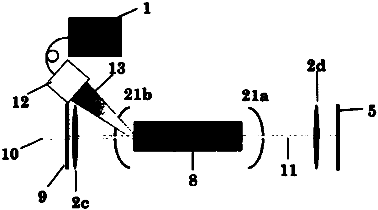
Cascaded pumping module and laser of a kind of resonant cavity
A cascaded pump and resonant cavity technology, applied in the field of optoelectronics, can solve the problems of no way for pump light to enter the optical fiber, poor beam quality, low brightness, etc., to achieve the improvement of light-to-light conversion efficiency, increase output power, and increase brightness Effect
- Summary
- Abstract
- Description
- Claims
- Application Information
AI Technical Summary
Problems solved by technology
Method used
Image
Examples
Embodiment 1
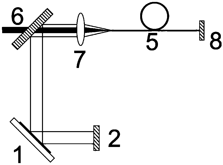
[0035] figure 2 It is a schematic diagram of a pumping device coupled with a disk and a spherical lens group involved in a cascaded pumping module of a resonant cavity according to an embodiment of the present invention. Such as figure 1 As shown, the optical device includes a disc 1 , a reflector 2 , a second dichroic mirror 6 , a focusing mirror 7 , a gain fiber 5 and a reflector 8 .
[0036] The material of disc 1 is Yb:YAG crystal, which has a diameter of 15mm and a thickness of 200um. The back of the disc is coated with a high-reflection film. Mirror 2 is a 1030nm high-reflection mirror with a reflectivity of 99.9% and a radius of curvature of 2m; the dichroic mirror 6 is a 1030nm high-reflection and 1080nm high-transmission plane mirror with a reflectivity of 99.9% and a transmittance of 99.9%; the focusing mirror 7 has a diameter of 15mm , a focusing lens with an effective focal length of 17mm; the gain fiber 5 is a Yb-doped double-clad silica fiber, the core diamete...
Embodiment 2
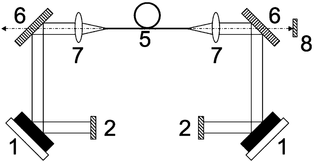
[0047] image 3 It is a schematic diagram of a pumping device coupled with two disks and a spherical lens group involved in a cascaded pumping module of a resonant cavity according to an embodiment of the present invention. Such as image 3 As shown, the pump module includes 2 discs 1 , 2 mirrors 2 , a first dichroic mirror 3 and a first dichroic mirror 6 , two focusing mirrors 7 , a gain fiber 5 , and a mirror 8 .
[0048] Among them, the material of disc 1 is Yb:YAG crystal with a diameter of 15mm and a thickness of 200um. The back of the disc is coated with a high-reflection film. The corresponding wavelengths of the film system are 940nm and 1030nm, and the reflectivity is 99.9% and 99.9% respectively. Reflector 2 is a 1030nm high-reflection mirror with a reflectivity of 99.9% and a radius of curvature of 2m; the dichroic mirror 6 is a 1030nm high-reflection and 1080nm high-transmission flat mirror with a reflectivity of 99.9% and a transmittance of 99.9%; focusing mirror...
Embodiment 3
[0053] Figure 4 It is a schematic diagram of a pumping device coupled with a disc and a parabolic mirror involved in a cascaded pumping module of a resonant cavity according to an embodiment of the present invention. Such as Figure 4 As shown, the pump module includes a disc 1 , a reflector 2 , a first dichroic mirror 3 , a parabolic reflector 4 , a gain fiber 5 , and a reflector 8 .
[0054] Among them, the material of disc 1 is Yb:YAG crystal with a diameter of 15mm and a thickness of 200um. The back of the disc is coated with a high-reflection film. The corresponding wavelengths of the film system are 940nm and 1030nm, and the reflectivity is 99.9% and 99.9% respectively. Reflector 2 is a 1030nm high reflection mirror with a reflectivity of 99.9% and a radius of curvature of 2m; the dichroic mirror 3 is a plane mirror with 1030nm high transparency and 1080nm high reflection, with a transmittance of 99.9% and a reflectivity of 99.9%; The focal length of the mirror is 50m...
PUM
 Abstract
Description
Claims
Application Information
 - R&D
- Intellectual Property
- Life Sciences
- Materials
- Tech Scout
- Unparalleled Data Quality
- Higher Quality Content
- 60% Fewer Hallucinations
Browse by: Latest US Patents, China's latest patents, Technical Efficacy Thesaurus, Application Domain, Technology Topic, Popular Technical Reports.
© 2025 PatSnap. All rights reserved.Legal|Privacy policy|Modern Slavery Act Transparency Statement|Sitemap|About US| Contact US: help@patsnap.com


