Rear-arranged impunity removing device of high speed steel wire production line

A production line and steel wire technology, applied in the field of high-speed steel, can solve the problems affecting the performance of high-speed steel, and achieve the effect of high qualification rate, clean production process and clean products

Pending Publication Date: 2017-06-09
江苏伟建工具科技有限公司
View PDF0 Cites 3 Cited by
  • Summary
  • Abstract
  • Description
  • Claims
  • Application Information

AI Technical Summary

Problems solved by technology

After quenching, because the internal structure still retains a part (about 30%) of the retained austenite and has not transformed into martensite, which affects the performance of high-speed steel

Method used


Image

  • Rear-arranged impunity removing device of high speed steel wire production line

Examples


Embodiment 1

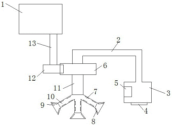
[0023] Embodiment one: if figure 1 As shown, a device for removing impurities at the rear of a high-speed steel wire production line includes a motor 1, a motor shaft 13 is arranged below the motor 1, and a driving wheel 12 is arranged at the end of the motor shaft 13. The driving wheel 12 and the driven wheel 6 rotate, from A hollow rotating shaft is provided below the driving wheel 6, a transmission shaft 2 is provided above the driven wheel 6, and a storage box 3 is provided at the other end of the transmission shaft 2, and a shunt 7 is connected to the end of the hollow rotating shaft 11, and a cover 9 is provided at the end of the shunt 7 , The inside of the middle separator and the cover 9 is provided with an iron filings attractor 8 . The motor shaft 13 is driven by the motor 1 to rotate, so that the driving wheel 12 drives the driven wheel 6 to rotate. After the driven wheel 6 rotates, the cover 9 at the end of the diverter 7 can contact a larger area as much as possib...

Embodiment 2

[0024] Embodiment 2: a device for removing impurities at the rear of a high-speed steel wire production line, including a motor 1, a motor shaft 13 is arranged below the motor 1, and a driving wheel 12 is arranged at the end of the motor shaft 13, and the driving wheel 12 and the driven wheel 6 rotate. A hollow rotating shaft is arranged below the driven wheel 6, and a transmission shaft 2 is arranged above the driven wheel 6. The other end of the transmission shaft 2 is provided with a storage box 3. The end of the hollow rotating shaft 11 is connected with a flow divider 7, and the end of the flow divider 7 is provided with a cover. 9. An iron filings attractor 8 is provided inside the middle separator and the cover 9 . The motor shaft 13 is driven by the motor 1 to rotate, so that the driving wheel 12 drives the driven wheel 6 to rotate. After the driven wheel 6 rotates, the cover 9 at the end of the diverter 7 can contact a larger area as much as possible to ensure that the...

Embodiment 3

[0027] Embodiment 3: A device for removing impurities at the rear of a high-speed steel wire production line, including a motor 1, a motor shaft 13 is arranged below the motor 1, and a driving wheel 12 is arranged at the end of the motor shaft 13, and the driving wheel 12 and the driven wheel 6 rotate. A hollow rotating shaft is arranged below the driven wheel 6, and a transmission shaft 2 is arranged above the driven wheel 6. The other end of the transmission shaft 2 is provided with a storage box 3. The end of the hollow rotating shaft 11 is connected with a flow divider 7, and the end of the flow divider 7 is provided with a cover. 9. An iron filings attractor 8 is provided inside the middle separator and the cover 9 . The motor shaft 13 is driven by the motor 1 to rotate, so that the driving wheel 12 drives the driven wheel 6 to rotate. After the driven wheel 6 rotates, the cover 9 at the end of the diverter 7 can contact a larger area as much as possible to ensure that the...


PUM


Abstract

The invention discloses a rear-arranged impunity removing device of a high speed steel wire production line. The device comprises a motor, a motor shaft is arranged below the motor, the tail end of the motor shaft is provided with a driving wheel, the driving wheel drives a driven wheel to rotate, a hollow rotation shaft is arranged below the driven wheel, a transmission shaft is arranged above the driven wheel, the other end of the transmission shaft is provided with a storage box, the tail end of the hollow rotation shaft is connected to a diverter, the tail end of the diverter is provided with a cover, and iron scrap suction apparatuses are arranged inside the diverter and the cover. The rear-arranged impunity removing device of the high speed steel wire production line has the advantages that the structure is reasonable, impunities can be removed comprehensively, the efficiency is higher, and the service life is longer.

Description

technical field [0001] The invention relates to the field of high-speed steel, in particular to a device for removing impurities behind a high-speed steel wire production line. Background technique [0002] High-speed steel wire is also known as wind steel or front steel, which means that it can be hardened even if it is cooled in air during quenching, and it is very sharp. It is a complex alloy steel containing carbide forming elements such as tungsten, molybdenum, chromium and vanadium. The total amount of alloying elements is about 10-25%. It can still maintain high hardness under the condition of high heat generated by high-speed cutting (about 500°C), and its HRC can be above 60. This is the most important characteristic of high-speed steel - red hardness. After quenching and low-temperature tempering, carbon tool steel has high hardness at room temperature, but when the temperature is higher than 200°C, the hardness drops sharply, and the hardness has dropped to a l...

Claims


Application Information

Patent Timeline
Patent Type & Authority Applications(China)
IPC IPC(8): B08B15/04C21D9/52
CPCB08B15/04C21D9/525Y02P10/20
Inventor 王卫和
Owner 江苏伟建工具科技有限公司
Why Eureka
Try Eureka