
Landfill leachate treatment process and special equipment thereof

A landfill leachate and treatment process technology, which is applied in the field of wastewater treatment, can solve the problems of high investment, difficult discharge standards, and high energy consumption, and achieve the effects of improving ammonia nitrogen discharge standards, alleviating pollution problems, and improving biodegradability

Pending Publication Date: 2017-06-09
深圳能源资源综合开发有限公司 +1
View PDF4 Cites 1 Cited by
  • Summary
  • Abstract
  • Description
  • Claims
  • Application Information

AI Technical Summary

Problems solved by technology

[0004] The purpose of the present invention is to provide a landfill leachate treatment process and its special equipment to solve the problem of high energy consumption, low efficiency, high investment, The problem that the effluent water quality is difficult to meet the standard alleviates the pollution problem of landfill leachate treatment, effectively improves the biodegradability and ammonia nitrogen discharge, and operates stably. At the same time, the obtained ammonium salt can be recycled.

Method used


Image

  • Landfill leachate treatment process and special equipment thereof
  • Landfill leachate treatment process and special equipment thereof

Examples


Embodiment 1

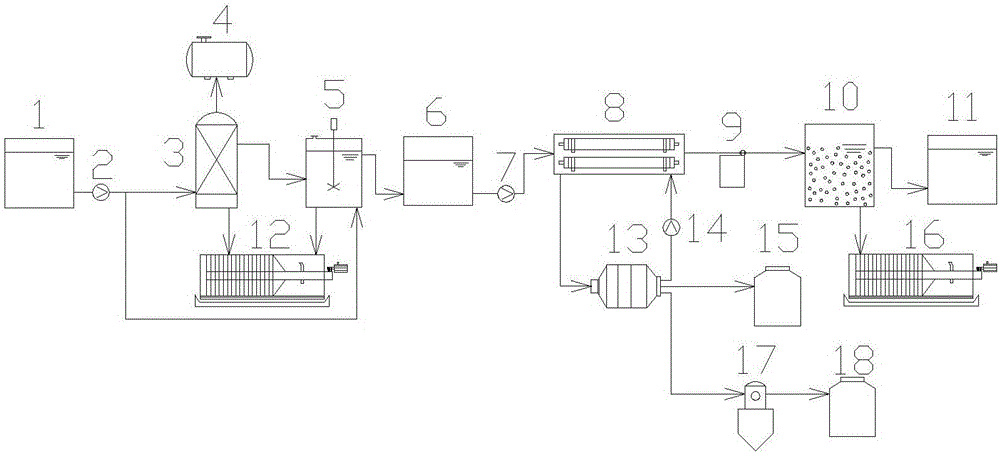
[0025] As attached figure 2 As shown, a special equipment for the treatment process of landfill leachate includes a raw water tank 1, a first inlet pump 2, an anaerobic reaction tank 3, a biogas collection system 4, a pretreatment reactor 5, an intermediate water tank 6, and a second inlet Water pump 7, membrane contactor unit 8, dosing pump 9, biochemical reaction tank 10, produced water tank 11, first sludge treatment system 12, acid absorption tank 13, acid absorption pump 14, first product tank 15, second sewage Sludge treatment system 16, crystallization device 17, and second product tank 18;

[0026] The raw water tank 1 is connected to the anaerobic reaction tank 3, the connecting pipeline is equipped with a first water inlet pump 2, the outlet end of the anaerobic reaction tank 3 is connected to the pretreatment reactor 5, and the sludge output end is connected to the first sludge treatment system 12. The biogas output end is connected to the biogas collection system 4,...

Embodiment 2

[0028] When the feed is landfill leachate, the raw water tank can also be directly connected to the pretreatment reactor 5.

[0029] The process of using the above-mentioned special equipment for landfill leachate treatment includes the following steps:

[0030] (1) The waste leachate of the incineration plant is anaerobic treated to obtain the anaerobic treated effluent. If it is landfill leachate, the anaerobic treatment will not be carried out and go directly to the next step; the COD content of the anaerobic treated effluent is 3000 -5000mg / L, NH 3 -N content is 1500-3000mg / L, hardness is 1000-2000mg / L, alkalinity is 6000-12000mg / L, and pH is in the range of 6.5-8.5.

[0031] (2) Pretreat the effluent obtained in step (1) to obtain chemical pretreatment effluent; the pretreatment is performed by adding lime CaOH 2 Or sodium hydroxide NaOH adjusts the pH to the range of 10-12 to perform a sufficient reaction to convert the ammonium ion in the wastewater into free ammonia, and remo...


PUM


Abstract

The invention relates to landfill leachate treatment process and special equipment thereof. The landfill leachate treatment process comprises the following steps: performing anaerobic treatment on landfill leachate of an incineration plant, pretreating the obtained effluent, and performing degassing membrane filtration and acid absorption on the pretreated effluent. By the technology, the problem of pollution caused by landfill leachate treatment is relieved, biodegradability is effectively improved, up-to-standard discharge of ammonia nitrogen is realized, operating stability is achieved, and the obtained ammonia salt can be recycled.

Description

Technical field [0001] The invention belongs to the technical field of wastewater treatment, and specifically relates to a landfill leachate treatment process and its special equipment. Background technique [0002] With the rapid development of cities, the output of urban waste is increasing. At present, the main treatment methods of municipal waste are landfill and incineration, and the use of both methods is accompanied by the production of landfill leachate. Landfill leachate is a high-concentration organic wastewater with complex components. It contains a lot of toxic and harmful substances, ammonia nitrogen and heavy metal ions, and the water quality and volume change greatly, which is difficult to handle, and will cause serious harm to the environment and the human body. Therefore, the control and treatment of landfill leachate are essential and vital. [0003] The technologies for treating leachate at home and abroad include land treatment, biological treatment, physical...

Claims


Application Information

Patent Timeline
IPC IPC(8): C02F9/14C01C1/16C01C1/242C02F101/16C02F103/06
CPCC01C1/164C01C1/242C02F9/00C02F3/28C02F2103/06C02F2101/16C02F2209/06C02F2209/14C02F1/66C02F3/00C02F1/44Y02E50/30
Inventor 兰建伟夏俊方赵剑锋方小琴江晶张萌苏志峰王然郑忆枫
Owner 深圳能源资源综合开发有限公司
Learn More