System used for combustion of aluminum powder or magnesium powder and recovery of product generated during combustion
A product, magnesium powder technology, applied in the direction of fuel system, charging system, combustion engine, etc., can solve the problems of not reducing pollution, not reducing carbon emissions, and increasing the overall damage to the environment, so as to eliminate emissions and reduce air pollution sources Effect
- Summary
- Abstract
- Description
- Claims
- Application Information
AI Technical Summary
Problems solved by technology
Method used
Image
Examples
Embodiment 1
[0123] Example 1 (Turn on the combustion subsystem)
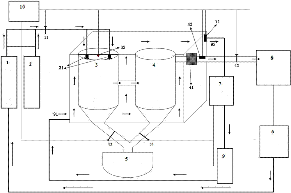
[0124] Turn on the controller 10, the aluminum powder is drawn from the fuel tank 2 by the aluminum powder pump, and the high-pressure air automatically flows out from the compressed air tank 1, and enters the combustion tank 3 through the one-way valve 11 and the nozzle 31 in a certain proportion with the aluminum powder; the total flow is controlled by The controller 10 is deployed; the controller 10 activates the igniter 32, and the aluminum powder starts to burn.
Embodiment 2
[0125] Embodiment 2 (Debugging the high-pressure gas automatic compensation storage subsystem)
[0126] The controller 10 is turned on, the combustion subsystem starts, and the aluminum powder starts to burn. High-pressure gas enters the gas storage tank 4 through the pipeline; the pressure of the gas storage tank 4 increases continuously, and the pressure is transmitted to the controller 10 through the pressure sensor 43 in real time, and the pressure threshold is set to 5.0×10 5 Pa (Petroleum pressure of gasoline internal combustion engine). When the pressure of the gas storage tank 4 reaches the set threshold, the controller 10 will automatically issue a command to stop the combustion subsystem; open the pressure control valve 42, and the pressure of the gas storage tank 4 will drop. 10 issues an instruction, the combustion subsystem starts to work, compensates for the pressure of the high-pressure gas storage system, and the external combustion engine starts to work continuous...
Embodiment 3
[0127] Example 3 (Debugging the cooling subsystem)
[0128] The controller 10 starts the cooling pump 9, the cooling water enters from the cooling liquid inlet 91, and reaches the radiator 7 through the external combustion cabinet and the cooling liquid outlet 92. After air cooling, the cooling water flows back to the cooling pump 9 to complete the cooling cycle. Set the monitoring temperature of the temperature sensor 71 to 90-95°C. When the temperature is lower than 90°C, the flow rate of the cooling pump 9 is reduced, and the cooling liquid rises; when the temperature is higher than 95°C, the flow rate of the cooling pump 9 is increased, and the cooling liquid cools down. ; Set the monitoring temperature of the temperature sensor 71 to 90-95℃, when the temperature is lower than 90℃, reduce the speed of the radiator 7 fan, and the coolant will heat up; when the temperature is higher than 95℃, increase the speed of the radiator 7 fan , Coolant cooling.
PUM
 Abstract
Description
Claims
Application Information
 - R&D
- Intellectual Property
- Life Sciences
- Materials
- Tech Scout
- Unparalleled Data Quality
- Higher Quality Content
- 60% Fewer Hallucinations
Browse by: Latest US Patents, China's latest patents, Technical Efficacy Thesaurus, Application Domain, Technology Topic, Popular Technical Reports.
© 2025 PatSnap. All rights reserved.Legal|Privacy policy|Modern Slavery Act Transparency Statement|Sitemap|About US| Contact US: help@patsnap.com


