Continuous heat-pipe roller vacuum drying machine

A drum vacuum and drying machine technology, applied in non-progressive dryers, drying solid materials without heating, dryers, etc., can solve the problem of inability to continuously vacuum dry materials, affect the drying quality of materials, and effectively heat energy Problems such as low utilization rate can achieve the effect of optimizing drying quality, improving effective utilization rate and reducing power

Inactive Publication Date: 2017-07-11
程长春
View PDF2 Cites 3 Cited by
  • Summary
  • Abstract
  • Description
  • Claims
  • Application Information

AI Technical Summary

Problems solved by technology

Existing dryers generally use coal and firewood as the heat source, which has high thermal efficiency loss and high heat transmission costs. The use of hot air is one-time, the effective utilization rate of heat energy is low, and the heat utilization is less than 30%. The drying of materials is uneven, which affects the quality of materials. drying quality
The circulating heat pipe drum vacuum dryer can only dry in batches, but cannot continuously vacuum dry materials, so further improvement is needed

Method used


Image

  • Continuous heat-pipe roller vacuum drying machine
  • Continuous heat-pipe roller vacuum drying machine
  • Continuous heat-pipe roller vacuum drying machine

Examples


Embodiment

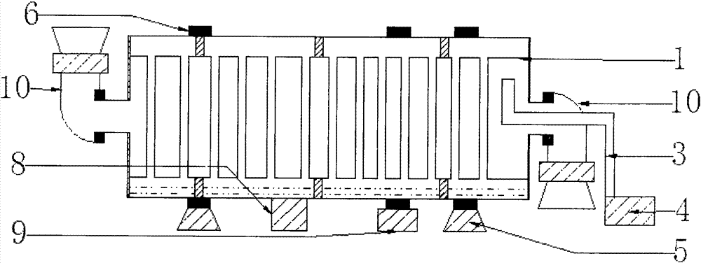
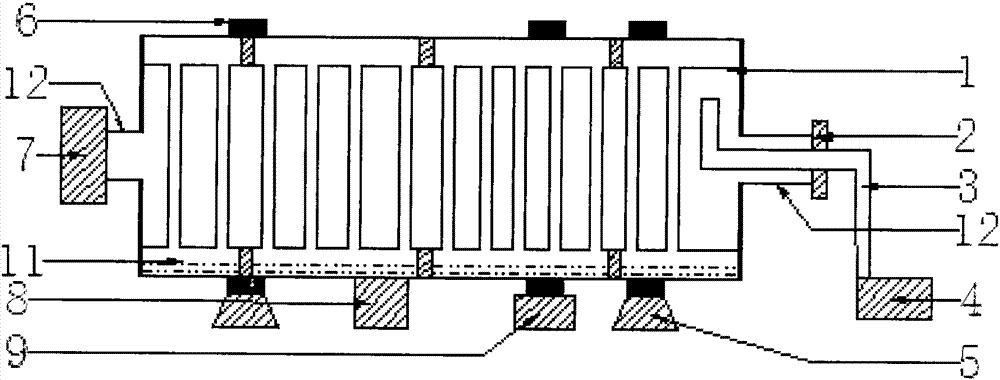
[0043] Such as figure 1 The shown continuous heat pipe drum vacuum dryer is composed of a circulating heat pipe drum vacuum dryer and a highly airtight unloading device (10).

[0044] The high airtight unloading device (10) is installed on the inlet and outlet (12) of the circulating heat pipe drum vacuum dryer.

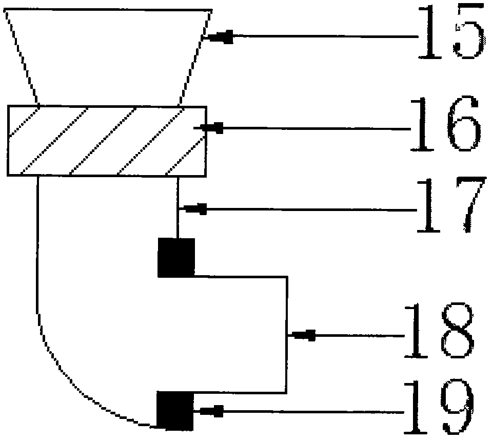
[0045] Such as figure 2 The shown high airtight unloading device (10) is made up of unloading device (16), elbow (17), sealing device (19), hopper (15) and conduit (18).

[0046] One end of the elbow (17) is connected to the discharge device (16), and the other end of the elbow (17) is connected to the conduit (18).

[0047] The conduit (18) and the elbow (16) are fixedly connected and sealed by a sealing device (19); the elbow (16) and the discharge device (18) are fixedly connected by a flange.

[0048] One end of the discharge device (18) is connected to the elbow (16), and the other end of the discharge device (18) is connected to the hopper (15).

[0049] S...


PUM


Abstract

A continuous heat pipe drum vacuum dryer of the present invention is composed of a circulating heat pipe drum vacuum dryer and a highly airtight unloading device. The high-airtight unloading device is installed on the inlet and outlet of the circulating heat pipe drum vacuum dryer. The material can continuously enter and exit the heat pipe drum. The vacuum unit maintains a certain degree of vacuum inside the heat pipe drum, and the water evaporates. The lower the boiling point, the less heat energy is needed to dry the material. The heat conducts heat and dissipates heat through the inner shell of the heat pipe drum and the heat dissipation pipe. The heat can conduct heat directly to the material, which improves the effective use of heat energy, enhances the drying efficiency of the material, and achieves the purpose of drying the material quickly. The heat dissipation pipe and the spiral blade have the function of stirring the material. During the drying process, the wet material is not easy to agglomerate, and the material has no drying dead angle, which optimizes the drying quality of the material and is a green drying that saves energy and reduces emissions.

Description

technical field [0001] The invention relates to a drum dryer, in particular to a continuous heat pipe drum vacuum dryer. Background technique [0002] Drum dryers currently on the market are suitable for drying large particles and large specific gravity materials in industries such as sawdust, distiller's grains, grain, rice husk, pasture, ore powder, coal slime, and coal powder. The drum of the drum dryer on the market is made of single-layer metal, and the hot air used is formed by heat exchange on the outside of the drum. It is necessary to use the negative pressure suction of the induced draft fan to pump the dried material into the drum for convection drying. Dry to achieve the effect of material drying. Existing dryers generally use coal and firewood as the heat source, which has high thermal efficiency loss and high heat transmission costs. The use of hot air is one-time, the effective utilization rate of heat energy is low, and the heat utilization is less than 30%....

Claims


Application Information

Patent Timeline
Patent Type & Authority Applications(China)
IPC IPC(8): F26B5/04F26B11/04F26B23/00F26B25/00
CPCF26B5/04F26B11/04F26B23/00F26B25/002
Inventor 程长春
Owner 程长春
Why Eureka
Try Eureka