
Clay foam composite system and method and device for applying clay foam composite system to oil-water well

A technology for oil-water wells and foam, which is applied in earthwork drilling, chemical instruments and methods, wellbore/well components, etc., can solve the problems of failure to meet the purpose of the measures, high cost of nano-scale solid particles, and slow drainage rate. Small and other problems, achieve the effect of uniform and delicate system, expand the sweep coefficient, and improve the fluidity

Inactive Publication Date: 2017-07-14
SHENGLI OILFIELD PETROLEUM DEV CENT +1
View PDF1 Cites 7 Cited by
  • Summary
  • Abstract
  • Description
  • Claims
  • Application Information

AI Technical Summary

Problems solved by technology

The solid phase particles are arranged in a wedge shape in the foam liquid film, and the liquid drainage rate on the plateau boundary of the bubble will be significantly reduced, and it will become an obstacle for the bubbles to merge with each other, increase the resistance of the fluid flow in the liquid film, improve the viscoelasticity and strength of the liquid film, and prolong the life of the liquid film. The half-life of the foam, the stability of the three-phase foam system can generally reach 10 to 30 times that of the corresponding two-phase foam, which has been greatly improved compared with the two foams, but for water plugging, profile control, and channel sealing processes, The validity period is far from meeting the purpose of the measures, and the cost of nano-scale solid phase particles is high, especially under the current situation of low oil prices, the application is greatly restricted

Method used


Image

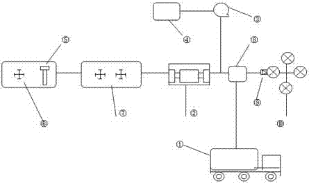
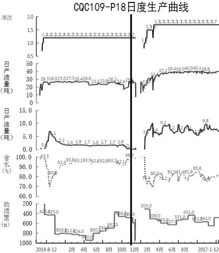
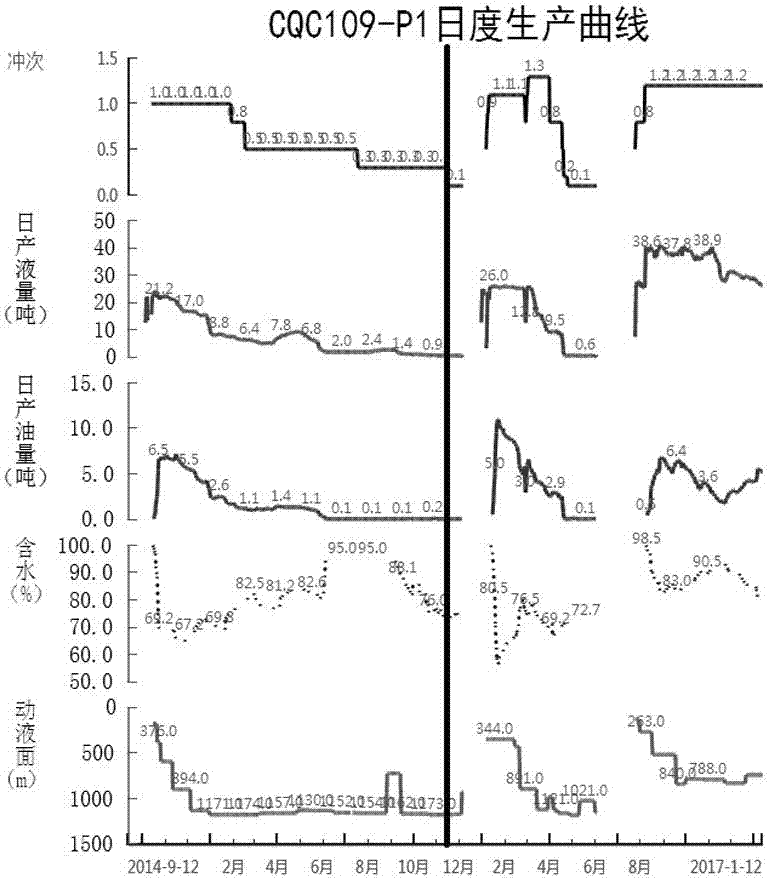
  • Clay foam composite system and method and device for applying clay foam composite system to oil-water well
  • Clay foam composite system and method and device for applying clay foam composite system to oil-water well
  • Clay foam composite system and method and device for applying clay foam composite system to oil-water well

Examples


Embodiment 1

[0045] Embodiment 1: A kind of clay foam composite system mentioned in the present invention is formed by uniform mixing of slurry and gas, wherein the slurry is composed of the following components in mass percentage:

[0046] (1) Solid particles: sodium bentonite, specification 400 mesh, 10%;

[0047] (2) Solid particles: oil well cement, specification 450 mesh, 2%;

[0048] (3) Dispersant: NaOH, 0.75%;

[0049] (4) Foaming agent: sodium lauryl sulfate, 1%;

[0050] (5) Stabilizer: Silicone amide, 1‰; Sodium silicate, modulus 3, 0.5%;

[0051] (6) The balance is fresh water;

[0052] Among them, the gas is nitrogen with a purity of ≥95%,

[0053] Among them, the ratio of gas to slurry is proportioned by volume, combined with formation pressure, the underground gas-to-slurry ratio is 1.5:1 (V 气体 :V 浆液 ).

[0054] The plugging mechanism of the composite system of the present invention is mainly composed of two parts: the plugging of the solid phase filler and the pl...

Embodiment 2

[0066] Embodiment 2: The difference between this embodiment and Embodiment 1 is that the second clay foam composite system is formed by uniformly mixing slurry and gas, wherein the slurry is composed of the following components in mass percentage:

[0067] (1) Solid particles: sodium bentonite, specification 200 mesh, 5%;

[0068] (2) Solid particles: oil well cement, specification 450 mesh, 0.5%;

[0069] (3) Dispersant: NaOH, 0.5%;

[0070] (4) Foaming agent: sodium lauryl sulfate, 0.5%;

[0071] (5) Stabilizer: Silicone amide, 0.5‰‰; Sodium silicate, modulus 2.4, 0.25%;

[0072] (6) The balance is fresh water.

[0073] Among them, the gas is nitrogen with a purity of ≥95%,

[0074] Among them, the ratio of gas and slurry is based on the volume ratio, combined with the formation pressure, the underground gas-slurry ratio is 2:1 (V 气体 :V 浆液 ).

[0075] In addition, the application method is as in Example 1 and will not be described in detail.

Embodiment 3

[0076] Embodiment 3, the difference between this embodiment and Embodiment 1 is: the second clay foam composite system is formed by uniformly mixing slurry and gas, wherein the slurry is composed of the following components in mass percentage:

[0077] (1) Solid particles: sodium bentonite, specification 600 mesh, 10%;

[0078] (2) Solid particles: oil well cement, specification 800 mesh, 5%;

[0079] (3) Dispersant: NaOH, 1%;

[0080] (4) Foaming agent: sodium lauryl sulfate, 1.5%;

[0081] (5) Stabilizer: Silicone amide, 1.5‰; Sodium silicate, modulus 3.3, 0.75%;

[0082] (6) The balance is fresh water.

[0083] Among them, the gas is nitrogen with a purity of ≥95%,

[0084] Among them, the ratio of gas and slurry is based on the volume ratio, combined with the formation pressure, the underground gas-slurry ratio is 1:1 (V 气体 :V 浆液 ).


PUM


Abstract

The invention relates to a clay foam composite system and a method and device for applying the clay foam composite system to an oil-water well. The clay foam composite system disclosed by the invention is prepared through uniformly mixing slurry and gas, wherein the slurry is prepared from the following ingredients: (1) sodium bentonite; (2) oil-well cement; (3) a dispersant: NaOH; (4) a foamer: sodium lauryl sulfate; (5) a stabilizer: 1) silicone amide; and 2) sodium silicate; and (6) the balance of fresh water; and the gas is nitrogen gas with the purity of not lower than 95%, the gas and the slurry are proportioned by volume, strata pressure is taken into account, and the underground gas / slurry ratio is (2: 1) to (1: 1). The clay foam composite system, the method and the device have the beneficial effects that a plugging mechanism of the composite system disclosed by the invention mainly comprises two parts, i.e., solid-phase filler plugging and gas-phase Jamin-effect plugging and has adjustable fluidity and permeability; due to solid particles, the strength of a liquid film can be enhanced; and meanwhile, an aqueous solution of the foamer in the system can be used for changing the wettability of rocks of strata on one hand and can also be used for reducing the viscosity of thick oil on the other hand, so that the fluidity of fluid of the strata is improved, and thus, the actions of reducing viscosity and helping displacement are achieved.

Description

technical field [0001] The invention relates to a process method for water plugging, profile control and channel sealing of oil-water wells in oil field production, in particular to a clay foam composite system and an application method and device for oil-water wells. Background technique [0002] In the middle and late stages of crude oil exploitation, development contradictions such as edge and bottom water intrusion and steam channeling in thermal recovery wells have become more and more serious, which has affected the recovery rate of crude oil. Professionals have adopted various control measures for this and achieved certain benefits. At present Commonly used methods for water plugging, profile control, and channel sealing mainly use plugging agent systems such as nitrogen foam, three-phase foam, jelly, resin, sediment, heavy oil, and inorganic composite particles. However, there are generally certain limitations. Among them, the organic plugging agent has the disadvant...

Claims


Application Information

Patent Timeline
IPC IPC(8): C09K8/467C09K8/506C09K8/518E21B33/13
CPCC09K8/426C09K8/467C09K8/506C09K8/518E21B33/13
Inventor 赵洪涛张明星裴春杜华霍刚王嘉敏范潇马涛蒋维红张安姜慧刘涛薛炳平赵林强
Owner SHENGLI OILFIELD PETROLEUM DEV CENT
Learn More