
Thermal power measurement device with visible-ultraviolet spectral measurement function

A measurement device and ultraviolet spectrum technology, applied in the field of thermal power measurement devices, can solve problems such as difficulty in obtaining strict correspondence between interaction and microstructure, inability to give spectral information, complex structure, etc., to improve light measurement efficiency and improve measurement efficiency. Efficiency, easy operation and quick effect

Active Publication Date: 2019-09-27
INST OF CHEM CHINESE ACAD OF SCI
View PDF7 Cites 0 Cited by
  • Summary
  • Abstract
  • Description
  • Claims
  • Application Information

AI Technical Summary

Problems solved by technology

This makes it often difficult to obtain a strict correspondence between interactions and microstructures by performing titration calorimetry and spectroscopic measurements separately.
[0003] Internationally, someone put the fiber optic probe into the reaction cell of the titration calorimeter to directly measure the change of solution turbidity (P. Johansson, I. Wadso, Thermochimica Acta 1999, 342, 19), but the optical measurement part has obvious Firstly, it cannot give detailed spectral information, and secondly, the optical fiber probe is directly immersed in the solution, and its structure is complex, which limits its use.

Method used


Image

  • Thermal power measurement device with visible-ultraviolet spectral measurement function
  • Thermal power measurement device with visible-ultraviolet spectral measurement function
  • Thermal power measurement device with visible-ultraviolet spectral measurement function

Examples


Embodiment Construction

[0019] The present invention will be described in detail below in conjunction with the accompanying drawings. However, it should be understood that the accompanying drawings are provided only for better understanding of the present invention, and they should not be construed as limiting the present invention.

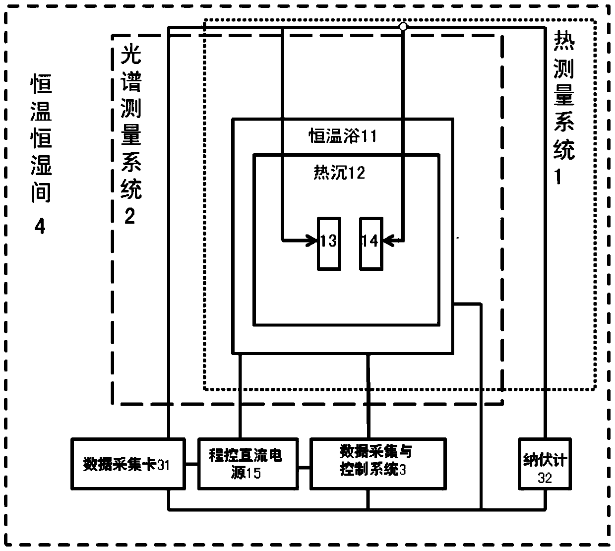
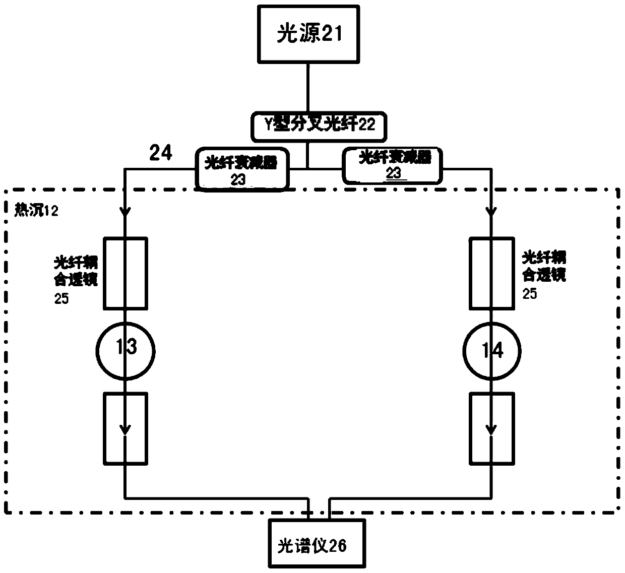
[0020] Solution reaction system of the present invention comprises solution and bottom liquid, all places bottom liquid (such as BSA in the specific embodiment) in the reaction pool of sample pool and reference pool before general experiment, the bottom liquid in the reaction pool of reference pool is constant , only as a reference for thermal measurement and optical measurement; solution (such as SDS in the embodiment) will be dripped into the reaction pool of the sample pool, and the bottom liquid in the reaction pool of the sample pool reacts with the dripping solution to release heat simultaneously, and the spectrum also Change accordingly.

[0021] Such as Figur...


PUM


Abstract

The invention relates to a thermal power measurement device with a visible-ultraviolet spectrum measurement function, which comprises a thermal measurement system, a spectrum measurement system, a data acquisition and control system, and a constant-temperature and constant-humidity room. The thermal measurement system is used for measuring the thermal power of a solution reaction system; the spectrum measurement system is used for measuring the visible-ultraviolet spectrum of the solution; the data acquisition and control system comprises a data acquisition device, a computer, and a nanovoltmeter, and a thermal measurement module, a spectrum module and a thermal measurement-spectrum combined module are arranged in the computer; the data acquisition unit is used for acquiring and sending the constant-temperature bath temperature of the thermal measurement system and current and voltage signals of a program-controlled direct-current power supply to the thermal measurement module, the nanovoltmeter is used for acquiring and sending a heat flow signal of the solution reaction system to the thermal measurement module, and the thermal measurement module is used for the calibration and thermal power measurement of the thermal measurement system; the spectrum module is used for acquiring and processing a spectrograph signal to implement the spectral signal measurement of the solution; and the thermal measurement-spectrum combined module is used for implementing the control of thermal power and spectral signal measurement.

Description

technical field [0001] The invention relates to a thermal power measuring device, in particular to a thermal power measuring device with a visible-ultraviolet spectrum measuring function. Background technique [0002] Thermal power measurement devices (ie, calorimeters) are widely used in scientific fields such as physics, chemistry, and biology, and in technical fields such as petrochemicals, secondary batteries, food processing, and pharmaceuticals. Among them, the isothermal titration calorimeter is especially suitable for the study of biological systems and weak interactions between molecules. Due to the complexity of such systems, spectroscopic measurements are generally supplemented to obtain microscopic information. Isothermal titration calorimetry can be used for multi-point continuous titration, and has the characteristics of concentration scanning. At present, instruments used for microstructure research, such as spectroscopy, are not designed to have this scanni...

Claims


Application Information

Patent Timeline
Patent Type & Authority Patents(China)
IPC IPC(8): G01N25/20G01N21/31
Inventor 张武寿赵海娜韩玉淳王毅琳
Owner INST OF CHEM CHINESE ACAD OF SCI
Learn More